以下答案仅供参考,有错欢迎
留言
。
Chapter 6:Drawing in Direct3D
提醒:记得多备份几份原书提供的BoxDemo.cpp和ShapeDemo.cpp,下面的题目基本上都由此基础上改动。
同类文章:
DirectX 11游戏编程学习笔记之8: 第6章Drawing in Direct3D(在Direct3D中绘制)(习题解答)
找到同类的文章实属不易,大家可以借鉴一番这篇文章(作者提供了完整的代码下载,而我比较懒。。下面只会说我大致的步骤)
勘误
:题中
D3D10_INPUT_ELEMENT_DESC更正为D3D11_…
1. Write down the D3D11_INPUT_ELEMENT_DESC array for the following vertex structure:
s
truct Vertex
{
XMFLOAT3 Pos;
XMFLOAT3 Tangent;
XMFLOAT3 Normal;
XMFLOAT2 Tex0;
XMFLOAT2 Tex1;
XMCOLOR Color;
};
D3D11_INPUT_ELEMENT_DESC    vertexDesc[] = {
{"POSITION", 0, DXGI_FORMAT_R32G32B32_FLOAT, 0, 0, D3D11_INPUT_PER_VERTEX_DATA, 0},
{"TANGENT", 0, DXGI_FORMAT_R32G32B32_FLOAT, 0, 12, D3D11_INPUT_PER_VERTEX_DATA, 0},
{"NORMAL", 0, DXGI_FORMAT_R32G32B32_FLOAT, 0, 24, D3D11_INPUT_PER_VERTEX_DATA, 0},
{"TEXCOORD", 0, DXGI_FORMAT_R32G32_FLOAT, 0, 36, D3D11_INPUT_PER_VERTEX_DATA, 0},
{"TEXCOORD", 1, DXGI_FORMAT_R32G32_FLOAT, 0, 44, D3D11_INPUT_PER_VERTEX_DATA, 0},
{"COLOR", 0, DXGI_FORMAT_R32G32B32A32_FLOAT, 0, 52, D3D11_INPUT_PER_VERTEX_DATA, 0}
};
2. Redo the Colored Cube demo, but this time use
two vertex buffers (and two input slots)
to feed the pipeline with
vertices, one that stores the position element and the other that stores the color element.
Your D3D11_INPUT_ELEMENT_DESC array will look like this:
D
3D11_INPUT_ELEMENT_DESC vertexDesc[] =
{
{“POSITION”, 0, DXGI_FORMAT_R32G32B32_FLOAT, 0, 0, D3D11_INPUT_PER_VERTEX_DATA, 0 },
{“COLOR”, 0, DXGI_FORMAT_R32G32B32A32_FLOAT, 1, 0, D3D11_INPUT_PER_VERTEX_DATA, 0 }
};
The position element is hooked up to input slot 0, and the color element is hooked up to input slot 1. Moreover
note that the D3D11_INPUT_ELEMENT_DESC::AlignedByteOffset is 0 for both elements; this is because the
position and color elements are no longer interleaved in a single input slot.
题目做起来其实比较麻烦:先说一下大概~首先题目要求使用2个Vertex Buffer以及2个input slot(最大可用个数为16,索引对应0~15)。好,记住了条件,我们来分析下装配顶点到渲染管线所用到的ID3D11DeviceContext::IASetVertexBuffers方法:
第一个参数StartSlot(UINT)表示从几号槽(槽即上述所说input slot的简称,范围是0到15号)开始计数,因为题目中POSITION占0号槽,COLOR占1号槽,所以从0号槽开始计数,StartSlot = 0。
第二个参数
NumBuffers(UINT)表示用到的buffer的个数,要求是2。建两个不同的VertexBuffer需要我们拆分原先的struct Vertex成两个,就像这样:
struct Vertex
{
	XMFLOAT3 Pos;
	XMFLOAT4 Color;
};

struct vertexPos
{
	XMFLOAT4 Color;
};

struct vertexColor
{
	XMFLOAT4 Color;
};
继续拆
:
	vertexPos vertexPos[] =
	{
			{ XMFLOAT3(-1.0f, -1.0f, -1.0f) },
			{ XMFLOAT3(-1.0f, +1.0f, -1.0f) },
			{ XMFLOAT3(+1.0f, +1.0f, -1.0f) },
			{ XMFLOAT3(+1.0f, -1.0f, -1.0f) },
			{ XMFLOAT3(-1.0f, -1.0f, +1.0f) },
			{ XMFLOAT3(-1.0f, +1.0f, +1.0f) },
			{ XMFLOAT3(+1.0f, +1.0f, +1.0f) },
			{ XMFLOAT3(+1.0f, -1.0f, +1.0f) }
	};

	vertexColor vertexColor[] =
	{
			{ (const float*)&Colors::White   },
			{ (const float*)&Colors::Black   },
			{ (const float*)&Colors::Red     },
			{ (const float*)&Colors::Green   },
			{ (const float*)&Colors::Blue    },
			{ (const float*)&Colors::Yellow  },
			{ (const float*)&Colors::Cyan    },
			{ (const float*)&Colors::Magenta }
	};
然后就简单了,对于Buffer的BUFFER_DESC,修改vbd.ByteWidth = sizeof(vertexPos) * 8;对于Buffer的SUBRESOURCE_DATA, 修改 vinitData.pSysMem = vertexPos;接着创建完这个存放位置信息的Buffer,我们再修改
vbd.ByteWidth = sizeof(vertexColor) * 8,
vinitData.pSysMem = vertexColor;,创建存放颜色信息的Buffer,就像这样:
    D3D11_BUFFER_DESC vbd;
    vbd.Usage = D3D11_USAGE_IMMUTABLE;
    vbd.ByteWidth = sizeof(vertexPos) * 8;
    vbd.BindFlags = D3D11_BIND_VERTEX_BUFFER;
    vbd.CPUAccessFlags = 0;
    vbd.MiscFlags = 0;
    vbd.StructureByteStride = 0;
    D3D11_SUBRESOURCE_DATA vinitData;
    vinitData.pSysMem = vertexPos;
    HR(md3dDevice->CreateBuffer(&vbd, &vinitData, &mBoxVB[0]));

    vbd.ByteWidth = sizeof(vertexColor) * 8;
    vinitData.pSysMem = vertexColor;
    HR(md3dDevice->CreateBuffer(&vbd, &vinitData, &mBoxVB[1]));
要学会节约,所以这里重复利用了一下vbd和vinitData。
你可能会发现我用的是mBoxVB[0]和
mBoxVB[1],而mBoxVB却是ID3D11Buffer*类型的。。别急,下面就会说到相应修改~
第三个参数ppVertexBuffers(ID3D11Buffer*const*)表示存放所有buffer地址的一个数组,那么我们肯定需要把建立好的两个Buffer放到数组里再传参,我的做法是把原有的成员变量ID3D11Buffer* mBoxVB修改为ID3D11Buffer* mBoxVB[2],当然你也可以用其他方式创建数组。那么相应地,要记得把构造函数初始化改为:mBoxVB[0] = nullptr, mBoxVB[1] = nullptr; 析构函数里改为:ReleaseCOM(mBoxVB[0]),ReleaseCOM(mBoxVB[1])。
第四个参数是pStrides(const UINT*),这个参数要求得到每个vertex buffer对应的vertex结构体大小,对于本题即pStrides = {sizeof(vertexPos), sizeof(vertexColor)}; // 12、16
第五个参数pOffsets
(const UINT*),它让装配顶点时可以忽略某些特定的顶点,比如本题操作到现在,mBoxVB里面有两个buffer,我们想让mBoxVB[0]里的所有顶点完整地装配到管线里,而mBoxVB[1]里需要把除第一个顶点之外的其他顶点装配到管线,那么pOffsets = {0,1}即可。
本题两个buffer中的顶点全部装配进去即可,所以让其为{0,0}。
	UINT stride[2] = {sizeof(vertexPos),sizeof(vertexColor)};
	UINT offset[2] = {0,0};
        md3dImmediateContext->IASetVertexBuffers(0, 2, mBoxVB, stride, offset);
突然发现已经解决了!所以说,这个问题的切入口就是仔细分析IASetVertexBuffers和要求,然后满足它!
我理解中的input slot:假如顶点包含很多信息(位置,颜色,法线,纹理坐标等),那么装配到管线的速度势必会慢上很多,而input slot的设定使得可以同时借助1~16个vertex buffer向管线装配同一个顶点的不同信息。而对于Index Buffer呢,因为都是整数嘛,数据量相比Vertex Buffer里的实在不值一提,所以也不用多个index buffer一起工作了,一个index buffer对于装配来说就足够高效了。
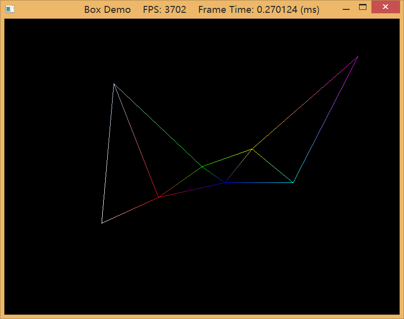
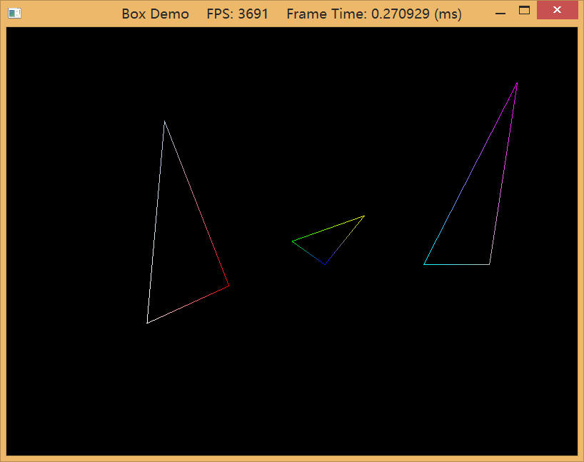
3. Draw
(a) a point list like the one shown in Figure 5.13a.
(b) a line strip like the one shown in Figure 5.13b.
(c) a line list like the one shown in Figure 5.13c.
(d) a triangle strip like the one shown in Figure 5.13d.
(e) a triangle list like the one shown in Figure 5.14a.
方便起见,我们用BoxDemo.cpp来修改
大致步骤如下:
1.为BoxApp类添加类成员变量: ID3D11RasterizerState* mWireframeRS (用于设置管线光栅化阶段的状态组);
然后在BoxApp::Init方法里设置其FillMode为线框模式(D3D11_FILL_WIREFRAME), 同时取消背面消隐(D3D11_CULL_NONE)。
	D3D11_RASTERIZER_DESC wireframeDesc;
	ZeroMemory(&wireframeDesc, sizeof(D3D11_RASTERIZER_DESC));
	wireframeDesc.FillMode = D3D11_FILL_WIREFRAME;
	wireframeDesc.CullMode = D3D11_CULL_NONE;
	//wireframeDesc.FrontCounterClockwise = false;
	//wireframeDesc.DepthClipEnable = true;

	HR(md3dDevice->CreateRasterizerState(&wireframeDesc, &mWireframeRS));
2.修改BuildGeometryBuffers方法:删去IndexBuffer的创建代码(不删也可以,因为可以选择不装配到管线嘛),本题只用到8个顶点(特别注意TriangleList方式需要用到9个,故此时D3D11_BUFFER_DESC.ByteWidth, Draw方法都需要修改8->9),图形也很简单,只使用VertexBuffer。
void BoxApp::BuildGeometryBuffers()
{
    // Create vertex buffer
    Vertex vertices[] =
    {
		{ XMFLOAT3(-0.5f, -0.4f, 0.0f), (const float*)&Colors::White   },
		{ XMFLOAT3(-0.3f, +0.4f, 0.0f), (const float*)&Colors::LightSteelBlue   },
		{ XMFLOAT3(-0.2f, -0.2f, 0.0f), (const float*)&Colors::Red     },
		{ XMFLOAT3( 0.0f, 0.0f, 0.0f), (const float*)&Colors::Green   },
		{ XMFLOAT3(+0.1f, -0.1f, 0.0f), (const float*)&Colors::Blue    },
		{ XMFLOAT3(+0.2f, +0.1f, 0.0f), (const float*)&Colors::Yellow  },
		{ XMFLOAT3(+0.4f, -0.1f, 0.0f), (const float*)&Colors::Cyan    },
		{ XMFLOAT3(+0.5f, +0.5f, 0.0f), (const float*)&Colors::Magenta },
		// triangle list需要的第九个顶点:
		// { XMFLOAT3(+0.6f, -0.1f, 0.0f), (const float*)&Colors::Silver}
    };

    D3D11_BUFFER_DESC vbd;
    vbd.Usage = D3D11_USAGE_IMMUTABLE;
    vbd.ByteWidth = sizeof(Vertex) * 8;  // 使用triangle list更改为9
    vbd.BindFlags = D3D11_BIND_VERTEX_BUFFER;
    vbd.CPUAccessFlags = 0;
    vbd.MiscFlags = 0;
	vbd.StructureByteStride = 0;
    D3D11_SUBRESOURCE_DATA vinitData;
    vinitData.pSysMem = vertices;
    HR(md3dDevice->CreateBuffer(&vbd, &vinitData, &mBoxVB));
}
3.修改DrawScene方法:修改下背景色(白或黑)以方便观察;删去装配IndexBuffer到管线的代码;IASetPrimitiveTopology根据不同的图元类型修改, DrawIndexed换为使用Draw,最后在画之前不要忘记设置光栅化阶段(Rasterization Stage,RS)哦,因为前面只是创建了一个Rasterizer State,还没Set到管线。
md3dImmediateContext->RSSetState(mWireframeRS);
———————————————————
部分截图
——————————————————————————————————-
TriangleStrip:
TriangleList:
——————————————————————————————————————————————————————————-
勘误
:tip vertex印刷错误,改为top vertex.
4. Construct the vertex and index list of a pyramid, as shown in Figure 6.19, and draw it. Color the base vertices green and the top vertex red.
在BoxDemo.cpp的基础上,改动VertexBuffer和IndexBuffer的数据,再相应修改下相关联函数的参数即可。
void BoxApp::BuildGeometryBuffers()
{
	// Create vertex buffer
    Vertex vertices[] =
    {
		{ XMFLOAT3(-1.0f, -1.0f, -1.0f), (const float*)&Colors::Green },
		{ XMFLOAT3(+1.0f, -1.0f, -1.0f), (const float*)&Colors::Green },
		{ XMFLOAT3( 0.0f, +1.0f,  0.0f), (const float*)&Colors::Red   },
		{ XMFLOAT3(-1.0f, -1.0f, +1.0f), (const float*)&Colors::Green },
		{ XMFLOAT3(+1.0f, -1.0f, +1.0f), (const float*)&Colors::Green }
    };

    D3D11_BUFFER_DESC vbd;
    vbd.Usage = D3D11_USAGE_IMMUTABLE;
    vbd.ByteWidth = sizeof(Vertex) * 5;
    vbd.BindFlags = D3D11_BIND_VERTEX_BUFFER;
    vbd.CPUAccessFlags = 0;
    vbd.MiscFlags = 0;
    vbd.StructureByteStride = 0;
    D3D11_SUBRESOURCE_DATA vinitData;
    vinitData.pSysMem = vertices;
    HR(md3dDevice->CreateBuffer(&vbd, &vinitData, &mBoxVB));


	// Create the index buffer

	UINT indices[] = {
		// front face
		0, 2, 1,
		// back face
        3, 4, 2,
		// left face
		3, 2, 0,
		// right face
		1, 2, 4,
		// bottom face
	    0, 1, 4,
		0, 4, 3
	};

    D3D11_BUFFER_DESC ibd;
    ibd.Usage = D3D11_USAGE_IMMUTABLE;
    ibd.ByteWidth = sizeof(UINT) * 18;
    ibd.BindFlags = D3D11_BIND_INDEX_BUFFER;
    ibd.CPUAccessFlags = 0;
    ibd.MiscFlags = 0;
    ibd.StructureByteStride = 0;
    D3D11_SUBRESOURCE_DATA iinitData;
    iinitData.pSysMem = indices;
    HR(md3dDevice->CreateBuffer(&ibd, &iinitData, &mBoxIB));
}
方便观察,在UpdateScene里面让pyramid绕y轴旋转,添加如下代码:
	//
	// spin the pyramid:
	//
	XMMATRIX Ry;

	// incremement y-rotation angle each frame
	static float Y = 0.0f;
	Ry = XMMatrixRotationY(Y);
	Y += dt;

	// reset angle to zero when angle reaches 2*PI
	if( Y >= 6.28f )
		Y = 0.0f;

	// combine x- and y-axis rotation transformations.
	XMStoreFloat4x4(&mWorld, Ry);
5. Run the “Box” demo, and recall that we specified colors at the vertices only. Explain how pixel colors were
obtained for each pixel on the triangle.
这题只是对BoxDemo做文字解释:为什么对于渲染出的立方体,我们仅指定8个顶点的颜色就能让整个立方体表面上的所有像素都获取到颜色值。答案很明显,每个Pixel的颜色是通过附近顶点的颜色值做插值得到的,在<5.10.3 顶点属性插值>你可以找到更完整的说明。
6. Modify the Colored Cube demo by applying the following transformation to each vertex in the vertex shader prior
to transforming to world space.
vin.Pos.xy += 0.5f*sin(vin.Pos.x)*sin(3.0f*gTime);
vin.Pos.z *= 0.6f + 0.4f*sin(2.0f*gTime);
The gTime constant buffer variable corresponds to the current GameTimer::TotalTime() value. This will
animate the vertices as a function of time by distorting them periodically with the sine function.
步骤如下:
还是打开一份新的BoxDemo.cpp
1.修改Color.fx:
Ⅰ.在cbuffer里添加float型全局变量gTime,用于和C++应用程序代码交互。
Ⅱ.在VS(Vertex Shader)代码里添加如下代码已实现立方体”扭曲”的动画效果。
    vin.PosL.xy += 0.5f*sin(vin.PosL.x)*sin(3.0f*gTime);
    vin.PosL.z  *= 0.6f + 0.4f*sin(2.0f*gTime);
2.修改BoxDemo.cpp:
Ⅰ.为BoxApp类添加ID3DX11EffectScalarVariable* mfxTime变量。
Ⅱ.在BoxApp::BuildFX中将mfxTime变量和cbuffer里的gTime绑定(padding)。
mfxTime = mFX->GetVariableByName("gTime")->AsScalar();
Ⅲ.在BoxApp::Draw中通过计时器(D3DApp::mTimer)获取程序已经运行的时间(TotalTime)。
float totalTime = D3DApp::mTimer.TotalTime();
然后以赋值给mfxTime的方式间接为gTime赋值,因为两者已经绑定在一起(与C++里引用&的区别也许就是mfxTime是在系统内存(RAM)中,gTime是在GPU的内存中(VRAM))。
mfxTime->SetFloat(totalTime);
(录制的gif失真有点严重,实际上渲染出的表面很平滑)
7. Merge the vertices of a box and pyramid into one large vertex buffer. Also merge the indices of the box and
pyramid into one large index buffer (but do not update the index values). Then draw the box and pyramid one-by-one
using the parameters of ID3D11DeviceContext::DrawIndexed. Use the world transformation matrix so that the box and pyramid are disjoint in world space.
相比ShapesDemo来说,这个真是太简单了…
首先我们重新创建一个
大小为原先两个顶点数组的size之和的
顶点数组,然后把box和pyramid各自的顶点数组里的元素压入进去得到vertices,同样的方式得到indices,然后调用在DrawScene中分别对Box和Demo设置世界矩阵、绘制即可。
void BoxApp::BuildGeometryBuffers()
{
	// Box's vertexs
    Vertex vertices1[] =
    {
		{ XMFLOAT3(-1.0f, -1.0f, -1.0f), (const float*)&Colors::White   },
		{ XMFLOAT3(-1.0f, +1.0f, -1.0f), (const float*)&Colors::Black   },
		{ XMFLOAT3(+1.0f, +1.0f, -1.0f), (const float*)&Colors::Red     },
		{ XMFLOAT3(+1.0f, -1.0f, -1.0f), (const float*)&Colors::Green   },
		{ XMFLOAT3(-1.0f, -1.0f, +1.0f), (const float*)&Colors::Blue    },
		{ XMFLOAT3(-1.0f, +1.0f, +1.0f), (const float*)&Colors::Yellow  },
		{ XMFLOAT3(+1.0f, +1.0f, +1.0f), (const float*)&Colors::Cyan    },
		{ XMFLOAT3(+1.0f, -1.0f, +1.0f), (const float*)&Colors::Magenta }

    };

	// Box's indices
	UINT indices1[] = {
		// front face
		0, 1, 2,
		0, 2, 3,

		// back face
		4, 6, 5,
		4, 7, 6,

		// left face
		4, 5, 1,
		4, 1, 0,

		// right face
		3, 2, 6,
		3, 6, 7,

		// top face
		1, 5, 6,
		1, 6, 2,

		// bottom face
		4, 0, 3,
		4, 3, 7
	};

	// pyramid's vertexs
    Vertex vertices2[] =
    {
		{ XMFLOAT3(-1.0f, -1.0f, -1.0f), (const float*)&Colors::Green   },
		{ XMFLOAT3(+1.0f, -1.0f, -1.0f), (const float*)&Colors::Green   },
		{ XMFLOAT3( 0.0f, +1.0f,  0.0f), (const float*)&Colors::Red    },
		{ XMFLOAT3(-1.0f, -1.0f, +1.0f), (const float*)&Colors::Green    },
		{ XMFLOAT3(+1.0f, -1.0f, +1.0f), (const float*)&Colors::Green }
    };

	// pyramid's indices
	UINT indices2[] = {
		// front face
		0, 2, 1,

		// back face
        3, 4, 2,

		// left face
		3, 2, 0,

		// right face
		1, 2, 4,

		// bottom face
	    0, 1, 4,
		0, 4, 3
	};

	vBoxCounts = ARRAYSIZE(vertices1);
	vPyramidCounts = ARRAYSIZE(vertices2);
	verticesCounts = vBoxCounts + vPyramidCounts;

    iBoxCounts = ARRAYSIZE(indices1);
	iPyramidCounts = ARRAYSIZE(indices2);
	indicesCounts = iBoxCounts + iPyramidCounts;

	std::vector<Vertex>  vertices;
	std::vector<UINT>    indices;

	for(UINT i = 0; i<vBoxCounts; ++i)
		vertices.push_back(vertices1[i]);

	for(UINT i = 0; i<iBoxCounts; ++i)
		indices.push_back(indices1[i]);

	for(UINT i = 0; i<vPyramidCounts; ++i)
		vertices.push_back(vertices2[i]);

	for(UINT i = 0; i<iPyramidCounts; ++i)
		indices.push_back(indices2[i] + vBoxCounts);

	// create vertex buffer
	D3D11_BUFFER_DESC vbd;
    vbd.Usage = D3D11_USAGE_IMMUTABLE;
    vbd.ByteWidth = sizeof(Vertex) * verticesCounts;
    vbd.BindFlags = D3D11_BIND_VERTEX_BUFFER;
    vbd.CPUAccessFlags = 0;
    vbd.MiscFlags = 0;
	vbd.StructureByteStride = 0;
    D3D11_SUBRESOURCE_DATA vinitData;
    vinitData.pSysMem = &vertices[0];
    HR(md3dDevice->CreateBuffer(&vbd, &vinitData, &mBoxVB));

	// create index buffer
	D3D11_BUFFER_DESC ibd;
    ibd.Usage = D3D11_USAGE_IMMUTABLE;
    ibd.ByteWidth = sizeof(UINT) * indicesCounts;
    ibd.BindFlags = D3D11_BIND_INDEX_BUFFER;
    ibd.CPUAccessFlags = 0;
    ibd.MiscFlags = 0;
	ibd.StructureByteStride = 0;
    D3D11_SUBRESOURCE_DATA iinitData;
    iinitData.pSysMem = &indices[0];
    HR(md3dDevice->CreateBuffer(&ibd, &iinitData, &mBoxIB));
}
void BoxApp::DrawScene()
{
md3dImmediateContext->ClearRenderTargetView(mRenderTargetView, reinterpret_cast<const float*>(&Colors::LightSteelBlue));
md3dImmediateContext->ClearDepthStencilView(mDepthStencilView, D3D11_CLEAR_DEPTH|D3D11_CLEAR_STENCIL, 1.0f, 0);
md3dImmediateContext->IASetInputLayout(mInputLayout);
md3dImmediateContext->IASetPrimitiveTopology(D3D11_PRIMITIVE_TOPOLOGY_TRIANGLELIST);
UINT stride = sizeof(Vertex);
UINT offset = 0;
md3dImmediateContext->IASetVertexBuffers(0, 1, &mBoxVB, &stride, &offset);
md3dImmediateContext->IASetIndexBuffer(mBoxIB, DXGI_FORMAT_R32_UINT, 0);
// Set constants
XMMATRIX view = XMLoadFloat4x4(&mView);
XMMATRIX proj = XMLoadFloat4x4(&mProj);
XMMATRIX viewProj = view*proj;
D3DX11_TECHNIQUE_DESC techDesc;
mTech->GetDesc( &techDesc );
for(UINT p = 0; p < techDesc.Passes; ++p)
{
// draw box
XMMATRIX world = XMLoadFloat4x4(&mWorld);
// 向左平移1.1f
XMMATRIX trans = XMMatrixTranslation(-1.1f, 0.0f, 0.0f);
world = XMMatrixMultiply(world,trans);
mfxWorldViewProj->SetMatrix(reinterpret_cast<float*>(&(world*viewProj)));
mTech->GetPassByIndex(p)->Apply(0, md3dImmediateContext);
md3dImmediateContext->DrawIndexed(iBoxCounts, 0, 0);
// draw box
world = XMLoadFloat4x4(&mWorld);
// 向右平移1.1f
trans = XMMatrixTranslation(+1.1f, 0.0f, 0.0f);
world = XMMatrixMultiply(world,trans);
mfxWorldViewProj->SetMatrix(reinterpret_cast<float*>(&(world*viewProj)));
mTech->GetPassByIndex(p)->Apply(0, md3dImmediateContext);
md3dImmediateContext->DrawIndexed(iPyramidCounts, iBoxCounts, 0);
}
HR(mSwapChain->Present(0, 0));
}
8. Modify the Colored Cube demo by rendering the cube in wireframe mode. Do this in two different ways:
First, by setting the rasterization render state from the C++ code by calling ID3D11DeviceContext::RSSetState;
second, by setting the rasterization render state from the effect file by calling SetRasterizerState() in the effect pass.
第一种方式: 详见前面第五题所述。
第二种方式: <6.8.1 Effects Files>的末尾有完整的示例。
9. Modify the Colored Cube demo by disabling backface culling (CullMode = None); also try culling front faces
instead of back faces (CullMode = Front). Do this in two different ways:
First, by setting the rasterization render state from the C++ code by calling ID3D11DeviceContext::RSSetState;
second, by setting the rasterization render state from the effect file by calling SetRasterizerState() in the effect pass. Output your results in wireframe mode so that you can see the difference.
在第八题的基础上改下参数即可。
10. If vertex memory is significant, then reducing from 128-bit color values to 32-bit color values may be worthwhile.
Modify the “Box” demo by using a 32-bit color value instead of a 128-bit color value in the vertex structure. Your
vertex structure and corresponding vertex input description will look like this:
struct Vertex{
XMFLOAT3 Pos;
XMCOLOR Color;
};
D3D11_INPUT_ELEMENT_DESC vertexDesc[] = {
{“POSITION”, 0, DXGI_FORMAT_R32G32B32_FLOAT, 0, 0, D3D11_INPUT_PER_VERTEX_DATA, 0},
{“COLOR”, 0, DXGI_FORMAT_R8G8B8A8_UNORM, 0, 12, D3D11_INPUT_PER_VERTEX_DATA, 0}
};
DXGI_FORMAT_R8G8B8A8_UNORM:
A four-component, 32-bit unsigned-normalized-integer format that supports 8 bits per channel including alpha.
那么比如说想设置顶点颜色为红色(以我们习惯的RGBA顺序), 我们写为0xff0000ff,试一下,确实是红色。
那么设置绿色试试,0x00ff00ff,发现没有, 是出乎意料的品红色(红+蓝)。如何解释这一现象呢?那当然是我们使用的cpu读取内存(由低地址到高地址)时没按RGBA顺序来读~
对于0x00ff00ff,从高位字节到低位字节是:0x00, 0xff, 0x00, 0xff。
内存中字节存储顺序一般为小端(即低位字节放低地址,高位字节放高地址),那么内存地址中由低到高存放的是: 0xff, 0x00, 0xff, 0x00,正好倒了过来,是红加蓝。
如果对于你的电脑,字节存储顺序是大端(与小端相反),那么内存地址中由低到高存放的是: 0x00, 0xff, 0x00, 0xff,将不会出现设置绿色,实际成品红色的问题。
所以为了表达RGBA,我们不得不以ABGR的形式表示我们的颜色。只有用ABGR,那么UINT数据存在内存里的顺序才会是R,G,B,A。
比如BoxDemo原先的顶点颜色,现在对应为:
	// Box's vertexs
    Vertex vertices1[] =
    {
		{ XMFLOAT3(-1.0f, -1.0f, -1.0f), 0xffffffff  },  // White
		{ XMFLOAT3(-1.0f, +1.0f, -1.0f), 0xff000000  },  // Black
		{ XMFLOAT3(+1.0f, +1.0f, -1.0f), 0xff0000ff  },  // Red
		{ XMFLOAT3(+1.0f, -1.0f, -1.0f), 0xff00ff00  },  // Green
		{ XMFLOAT3(-1.0f, -1.0f, +1.0f), 0xffff0000  },  // Blue
		{ XMFLOAT3(-1.0f, +1.0f, +1.0f), 0xff00ffff  },  // Yellow
		{ XMFLOAT3(+1.0f, +1.0f, +1.0f), 0xffffff00  },  // Cyan
		{ XMFLOAT3(+1.0f, -1.0f, +1.0f), 0xffff00ff  }   // Magenta

    };
ABGR是不是有点反逻辑呢?所以为了在写代码的时候方便指定颜色,我们可以自定义一种喜欢的描述顺序,然后定义一个转换函数或宏来转换到ABGR。
作者的话,青睐于ARGB来描述颜色,所以他在d3dUtil.h代码里定义了Convert::ArgbToAbgr(UINT argb)。
这样一来,作者就可以这样写:
	// Box's vertexs
    Vertex vertices1[] = {
		{ XMFLOAT3(-1.0f, -1.0f, -1.0f), Convert::ArgbToAbgr(0xffffffff)  },  // White
		{ XMFLOAT3(-1.0f, +1.0f, -1.0f), Convert::ArgbToAbgr(0xff000000)  },  // Black
		{ XMFLOAT3(+1.0f, +1.0f, -1.0f), Convert::ArgbToAbgr(0xffff0000)  },  // Red
		{ XMFLOAT3(+1.0f, -1.0f, -1.0f), Convert::ArgbToAbgr(0xff00ff00)  },  // Green
		{ XMFLOAT3(-1.0f, -1.0f, +1.0f), Convert::ArgbToAbgr(0xff0000ff)  },  // Blue
		{ XMFLOAT3(-1.0f, +1.0f, +1.0f), Convert::ArgbToAbgr(0xffffff00)  },  // Yellow
		{ XMFLOAT3(+1.0f, +1.0f, +1.0f), Convert::ArgbToAbgr(0xff00ffff)  },  // Cyan
		{ XMFLOAT3(+1.0f, -1.0f, +1.0f), Convert::ArgbToAbgr(0xffff00ff)  }   // Magenta

    };
但我觉得这样一来有点自找麻烦。。需要打的代码量增加了,函数调用次数也增多了。。仅仅为了按自己的argb风格来描述颜色。
不过如果说考虑到不同cpu类型、不同平台的电脑大小端会不同,那么这个argb的任性便有了意义:小端就用ArgbToAbgr, 大端就用ArgbToRgba。
11. Modify the “Skull” demo by changing the viewport to only render to a subrectangle of the output window.
在Chapter4里做过一次,当时是在D3DApp::OnResize()里修改的,这次玩点不同的。
把主窗口分成四个小窗口从不同角度来观察旋转中的骷髅头!
是不是挺像监控室里的大屏幕~

void SkullApp::DrawScene()
{
	md3dImmediateContext->ClearRenderTargetView(mRenderTargetView, reinterpret_cast<const float*>(&Colors::LightSteelBlue));
	md3dImmediateContext->ClearDepthStencilView(mDepthStencilView, D3D11_CLEAR_DEPTH|D3D11_CLEAR_STENCIL, 1.0f, 0);

	md3dImmediateContext->IASetInputLayout(mInputLayout);
    md3dImmediateContext->IASetPrimitiveTopology(D3D11_PRIMITIVE_TOPOLOGY_TRIANGLELIST);

	md3dImmediateContext->RSSetState(mWireframeRS);

	UINT stride = sizeof(Vertex);
    UINT offset = 0;
    md3dImmediateContext->IASetVertexBuffers(0, 1, &mVB, &stride, &offset);
	md3dImmediateContext->IASetIndexBuffer(mIB, DXGI_FORMAT_R32_UINT, 0);

	// Set constants
	XMMATRIX proj  = XMLoadFloat4x4(&mProj);
	XMMATRIX world = XMLoadFloat4x4(&mSkullWorld);

	XMMATRIX view;
	XMVECTOR pos;
	XMVECTOR target = XMVectorZero();
	XMVECTOR up     = XMVectorSet(0.0f, 1.0f, 0.0f, 0.0f);

    D3DX11_TECHNIQUE_DESC techDesc;
    mTech->GetDesc( &techDesc );
    for(UINT p = 0; p < techDesc.Passes; ++p)
    {
		// top left
		pos    = XMVectorSet(0.0f, 0.0f, 20.0f, 1.0f);
		view = XMMatrixLookAtLH(pos, target, up);
		mfxWorldViewProj->SetMatrix(reinterpret_cast<float*>(&(world*view*proj)));

		mScreenViewport.TopLeftX = 0.0f;
		mScreenViewport.TopLeftY = 0.0f;
		mScreenViewport.Width    = static_cast<float>(mClientWidth)/2;
		mScreenViewport.Height   = static_cast<float>(mClientHeight)/2;
		md3dImmediateContext->RSSetViewports(1, &mScreenViewport);

		mTech->GetPassByIndex(p)->Apply(0, md3dImmediateContext);
		md3dImmediateContext->DrawIndexed(mSkullIndexCount, 0, 0);


		// top right
		pos    = XMVectorSet(0.0f, 0.0f, -20.0f, 1.0f);
		view = XMMatrixLookAtLH(pos, target, up);
		mfxWorldViewProj->SetMatrix(reinterpret_cast<float*>(&(world*view*proj)));

		mScreenViewport.TopLeftX = static_cast<float>(mClientWidth)/2;
		mScreenViewport.TopLeftY = 0.0f;
		mScreenViewport.Width    = static_cast<float>(mClientWidth)/2;
		mScreenViewport.Height   = static_cast<float>(mClientHeight)/2;
		md3dImmediateContext->RSSetViewports(1, &mScreenViewport);

		mTech->GetPassByIndex(p)->Apply(0, md3dImmediateContext);
		md3dImmediateContext->DrawIndexed(mSkullIndexCount, 0, 0);

		// bottom left
		pos    = XMVectorSet(0.0f, 20.0f, 1.0f, 1.0f);
		view = XMMatrixLookAtLH(pos, target, up);
		mfxWorldViewProj->SetMatrix(reinterpret_cast<float*>(&(world*view*proj)));

		mScreenViewport.TopLeftX = 0.0f;
		mScreenViewport.TopLeftY = static_cast<float>(mClientHeight)/2;
		mScreenViewport.Width    = static_cast<float>(mClientWidth)/2;
		mScreenViewport.Height   = static_cast<float>(mClientHeight)/2;
		md3dImmediateContext->RSSetViewports(1, &mScreenViewport);

		mTech->GetPassByIndex(p)->Apply(0, md3dImmediateContext);
		md3dImmediateContext->DrawIndexed(mSkullIndexCount, 0, 0);


		// bottom right
		pos    = XMVectorSet(15.0f, -15.0f, 1.0f, 1.0f);
		view = XMMatrixLookAtLH(pos, target, up);
		mfxWorldViewProj->SetMatrix(reinterpret_cast<float*>(&(world*view*proj)));

		mScreenViewport.TopLeftX = static_cast<float>(mClientWidth)/2;
		mScreenViewport.TopLeftY = static_cast<float>(mClientHeight)/2;
		mScreenViewport.Width    = static_cast<float>(mClientWidth)/2;
		mScreenViewport.Height   = static_cast<float>(mClientHeight)/2;
		md3dImmediateContext->RSSetViewports(1, &mScreenViewport);

		mTech->GetPassByIndex(p)->Apply(0, md3dImmediateContext);
		md3dImmediateContext->DrawIndexed(mSkullIndexCount, 0, 0);
    }

	HR(mSwapChain->Present(0, 0));
}
UpdateScene中更新SkullWolrd矩阵以达到旋转旋转效果。
12. Consider the following C++ vertex structure:
struct Vertex
{
XMFLOAT3 Pos;
XMFLOAT4 Color;
};
(a) Does the input layout description order need to match the vertex structure order? That is, is the following vertex
declaration correct for this vertex structure? Do an experiment to find out. Then give reasoning for why you think it works or does not work.
D3D11_INPUT_ELEMENT_DESC vertexDesc[] =
{
{“COLOR”, 0, DXGI_FORMAT_R32G32B32A32_FLOAT, 0, 12, D3D11_INPUT_PER_VERTEX_DATA, 0},
{“POSITION”, 0, DXGI_FORMAT_R32G32B32_FLOAT, 0, 0, D3D11_INPUT_PER_VERTEX_DATA, 0}
};
经实验,这样做程序没有影响。我觉得顶点描述vertexDesc里的每一个元素是通过字节偏移量来对应顶点结构体struct Vertex里的成员的,而非通过数组索引(例如,vertexDesc[0]对应Vertex结构体中第一个成员这种方式)。字节偏移量呢,就是UINT AlignedByteOffset这个参数,但我不禁想到。。如果InputSlot存在多个对应各个成员,那么这时候字节偏移量都为0,又该如何判断?一个Slot对应一个VertexBuffer,而每个VertexBuffer都有各自的struct Vertex,所以Slot0和Slot1对应的是不同顶点结构体,也不矛盾。
(b) Does the corresponding vertex shader structure order need to match the C++ vertex structure order? That is,
does the following vertex shader structure work with the previous C++ vertex structure? Do an experiment to
find out. Then give reasoning for why you think it works or does not work.
struct VertexIn
{
float4 Color : COLOR;
float3 PosL : POSITION;
};
同样是没有影响的,见书中图6.1,vs中的每个元素对应顶点结构体是根据顶点描述里的[语义名字+索引(默认0)]来确定的,与结构体内定义顺序没关系。
13. We can submit an array of screen rectangles to the Direct3D scissor test. The scissor test will discard all pixels
outside the scissor rectangles. Modify the “Shapes” demo to use the scissor test. The scissor rectangles can be set
with the following method:
void RSSetScissorRects(UINT NumRects, const D3D11_RECT *pRects);
Here is an example call:
D3D11_RECT  rects ={100, 100, 400, 400};
md3dImmediateContext-> RSSetScissorRects(1,&rects);
The previous call only sets the scissor rectangles, but it does not enable the scissor test. The scissor test is
enabled/disabled via the D3D11_RASTERIZER_DESC::ScissorEnable.
相关MSDN文档:
ID3D10Device::RSSetScissorRects method
这道题很简单,但也要注意:
1.设置ScissorRects前记得通过修改D3D11_RASTERIZER_DESC开启Scissor功能, RSState可以在C++代码中
设置
,也可以在Shader里面设置。
C++:
	// ......
        wireframeDesc.ScissorEnable = true;

	HR(md3dDevice->CreateRasterizerState(&wireframeDesc, &mWireframeRS));
HLSL:
RasterizerState WireframeRS
{
    FillMode = Wireframe;
	CullMode = None;
	ScissorEnable = true;
};
2.设置多个ScissorRects时的话只在多个Viewport才有意义,窗口就像一张纸,Scissor就是剪刀工具,ScissorRect就是你要剪出来的矩形区域,剪n次最后还不是一个矩形。。不如一次到位。
Which scissor rectangle to use is determined by the SV_ViewportArrayIndex semantic output by a geometry shader (see
shader semantic syntax
).
If a geometry shader does not make use of the SV_ViewportArrayIndex semantic then Direct3D will use the first scissor rectangle in the array.
Each scissor rectangle in the array corresponds to a viewport in an array of viewports (see
ID3D10Device::RSSetViewports
).
看了文档,发现必须要使用Geometry Shader才能实现多ScissorRect对应多Viewport,而color.fx是SetGeometryShader( NULL )的,留待以后实验。
14. Modify the “Shape” demo to use GeometryGenerator::CreateGeosphere instead of
GeometryGenerator::CreateSphere. Try with 0, 1, 2, and 3 subdivision levels.
参照ShapeDemo的步骤来使用GeometryGenerator生成Vertex和Index的Buffer。
	GeometryGenerator::MeshData  sphere;
	GeometryGenerator geoGen;
	geoGen.CreateGeosphere(0.5f,3,sphere); // 0,1,2,3表示球表面的细分等级
  //geoGen.CreateSphere(0.5f, 20, 20, sphere); //半径0.5f,SliceCounts=20,StackCounts=20

	std::vector<Vertex> vertices(sphere.Vertices.size());
	for(size_t i = 0; i<sphere.Vertices.size(); ++i){
		vertices[i].Pos = sphere.Vertices[i].Position;
		vertices[i].Color = (const float*)&Colors::Blue;  // XMFLOAT4 blue(0.0f,0.0f,1.0f,1.0f);
	}
MeshData里的顶点数据的格式有Pos,Normal,Tangent,Texture等多种可选用,我们只获取Pos,同时还需要设定顶点的Color值。这样就完成了对VertexBuffer所需数据的加工,而IndexBuffer则直接使用&sphere.Indices[0]作数据源即可。