https://roystan.net/articles/toon-water.html
https://github.com/IronWarrior/ToonWaterShader
Toon Water Shader
>> using Unity engine 2018.3
50 minutes to complete
You will learn to write a toon water shader. You will use data from the depth and normals buffer to generate shoreline foam, and noise and distortion textures to render toon waves.
Water can be challenging to render and almost always requires a custom shader to bring to life. This is especially true for toon style water.
This article will outline techniques to render the most common components of a water shader:
shoreline foam
,
depth-based coloring
and
surface waves
. While this shader is designed for a toon look, the approach presented here can be adapted for any art style.
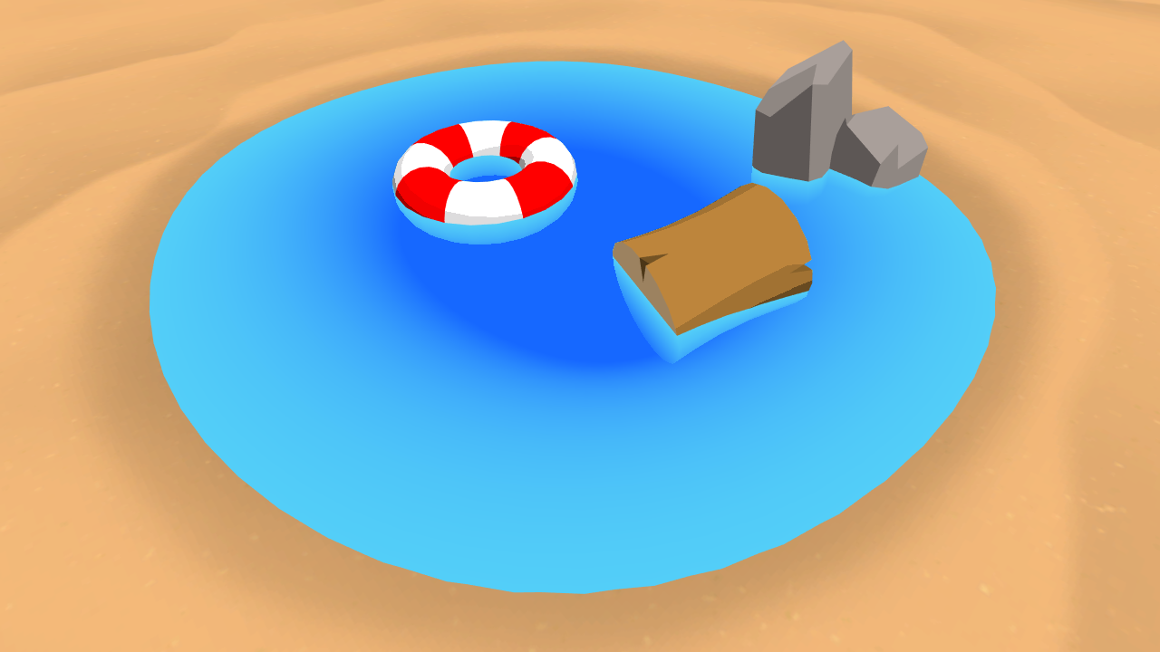
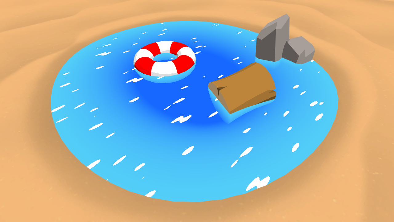
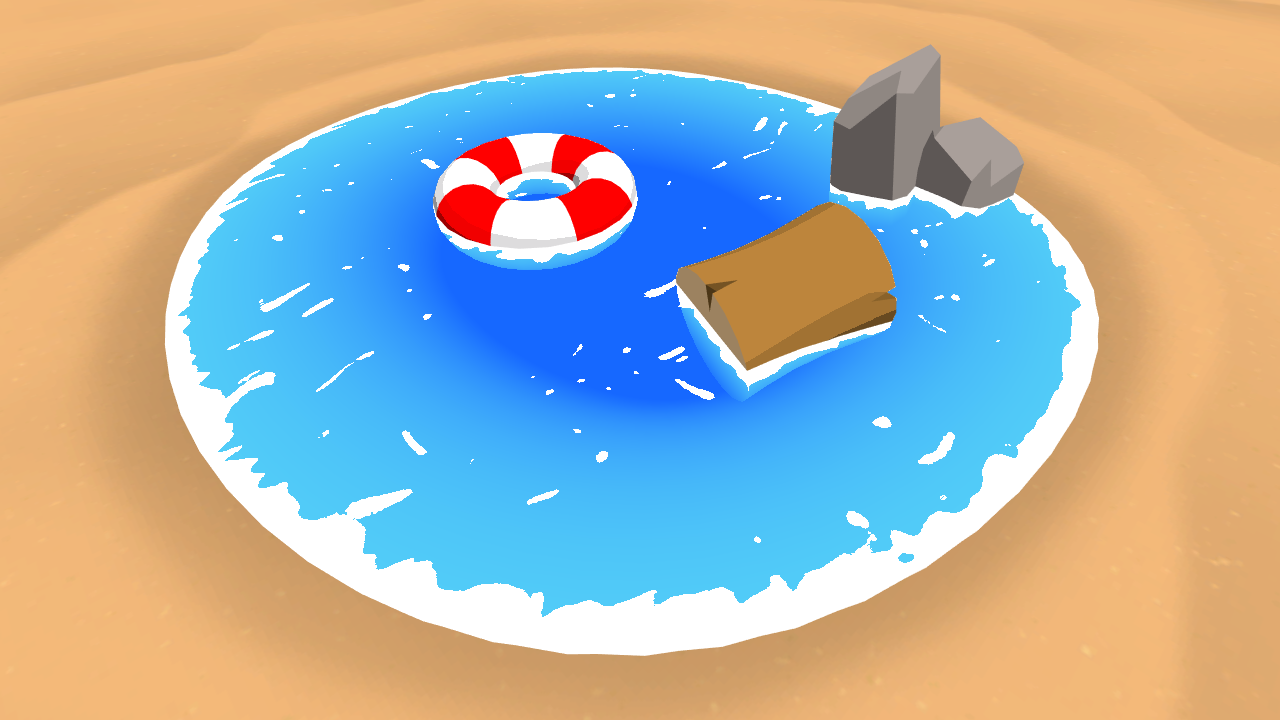
The completed project
is provided at the end of the article. Note that it also contains a large amount of comments in the created shader file to aid understanding.
Prerequisites
To complete this tutorial, you will need a working knowledge of Unity engine, and a basic understanding of shader syntax and functionality.
These tutorials are made possible, and kept
free
and
open source
, by your support. If you enjoy them, please consider becoming my
patron through Patreon
.
Getting started
Download the starter project provided above and open it in the Unity editor. Open the
Main
scene (located at the project root), and open the
ToonWater
shader (located in the
Shaders
directory) in your preferred code editor.
This file contains about the simplest shader possible: one that outputs the color white. We will build off this shader throughout this article to make it render toon style water.
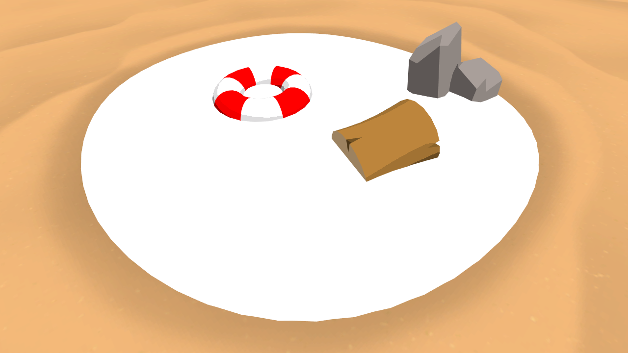
1. Depth based color
Water changes color depending on how deep it is, due to it absorbing light that passes through it. To reflect this, we will use a
gradient
to control our water’s color. What color is outputted from the gradient will be controlled by the
depth
of the objects under the water.
1.1 Properties and variables
Add the following three properties to the top of the shader.
_DepthGradientShallow("Depth Gradient Shallow", Color) = (0.325, 0.807, 0.971, 0.725)
_DepthGradientDeep("Depth Gradient Deep", Color) = (0.086, 0.407, 1, 0.749)
_DepthMaxDistance("Depth Maximum Distance", Float) = 1
Note that these properties already have some default values filled in; these are the values used for the material in the animated image at the top of this article.
We define our gradient with two colors, one for when our water is at its most shallow (i.e., when the object behind it is
nearly
touching the surface), and one for when it is at its deepest. Since it’s possible that our water could be infinity deep, we add the
_DepthMaxDistance
property as a cutoff for the gradient—anything deeper than this will no longer change color.
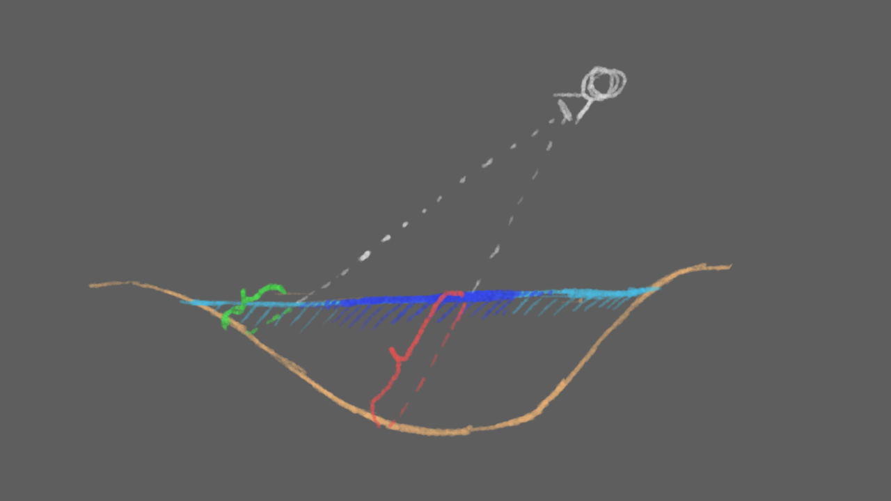
Side view of the beach scene. When the distance between the water and the ground is small (shown in green), the color of the water is lighter. When the distance is large (in red), the water is darker.
Before we can implement our gradient, we need to declare our properties in our
CGPROGRAM
. Add the following immediately above the fragment shader.
float4 _DepthGradientShallow;
float4 _DepthGradientDeep;

float _DepthMaxDistance;

sampler2D _CameraDepthTexture;
What are properties? What’s a fragment shader? I’m feeling lost!
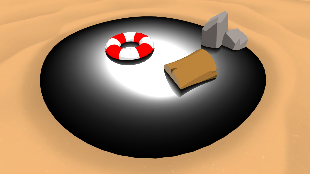
1.2 Calculating water depth
You might have noticed in the code block above the line declaring a
sampler2D
named
_CameraDepthTexture
. This declaration gives our shader access to a variable
not declared
in our properties: the camera’s
depth texture
. A depth texture is a
greyscale
image that colors objects based on their distance from the camera. In Unity, objects closer to the camera are more white, while objects further away are darker.
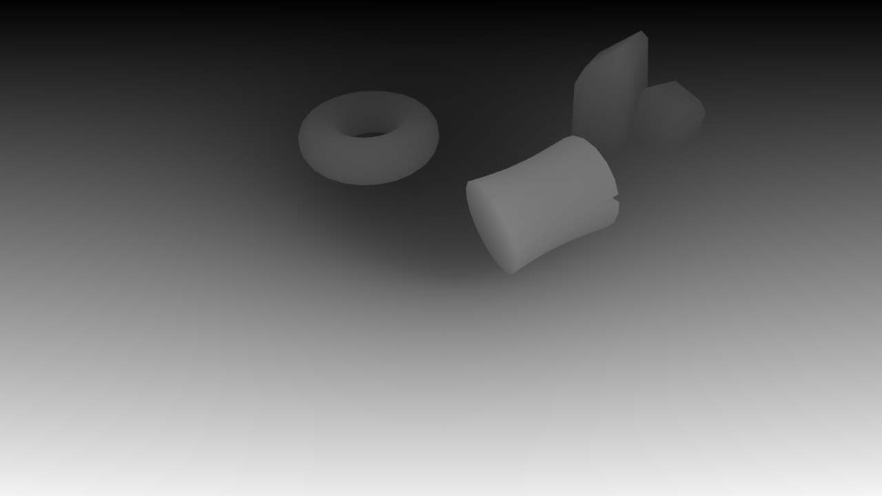
Depth texture for the beach scene, excluding the water. Note that the
Far
plane of the camera is much smaller than normal to better highlight the difference in greyscale values.
This
_CameraDepthTexture
variable is available globally to all shaders, but
not
by default; if you select the
Camera
object in the scene, you’ll notice that it has the script
CameraDepthTextureMode
attached, with it’s inspector field set to
Depth
. This script instructs the camera to render the depth texture of the current scene into the above shader variable.
The depth texture is a
full-screen
texture, in that it has the same dimensions as the screen we are rendering to. We want to sample this texture at the same position as the current pixel we’re rendering. To do this, we’ll need to calculate the
screen space position
of our vertex in the vertex shader, and then pass this value into the fragment shader where we can use it.
// Inside the v2f struct.
float4 screenPosition : TEXCOORD2;

…

// Inside the vertex shader.
o.screenPosition = ComputeScreenPos(o.vertex);
With the screen position accessible through the
v2f
struct, we can now sample the depth texture. Add the following code to the fragment shader.
float existingDepth01 = tex2Dproj(_CameraDepthTexture, UNITY_PROJ_COORD(i.screenPosition)).r;
float existingDepthLinear = LinearEyeDepth(existingDepth01);
The first line samples the depth texture using
tex2Dproj
and our screen position. This will return the depth of the surface behind our water, in a range of 0 to 1. This value is
non-linear
—one meter of depth very close to the camera will be represented by a comparatively larger value in the depth texture than one meter a kilometer away from the camera. The second line converts the non-linear depth to be linear, in world units from the camera.
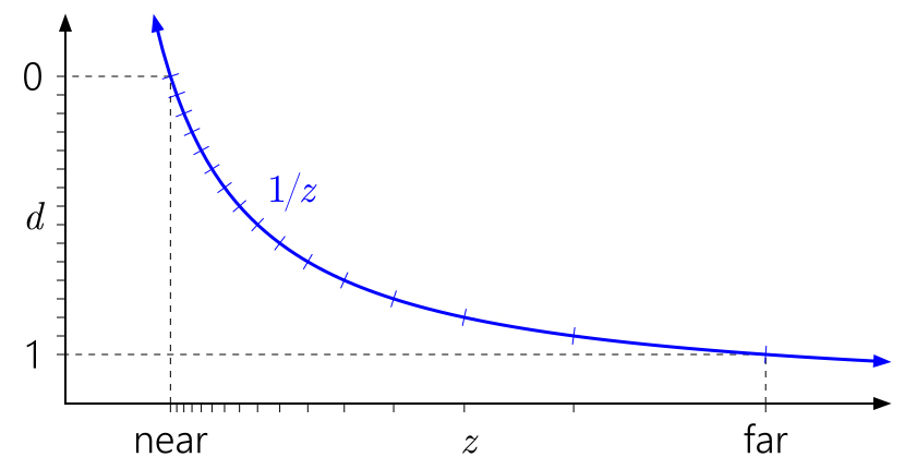
As we move left to right on this graph, further away from the camera, larger distances are represented by smaller values in the depth buffer. Image from
NVIDIA article on depth precision
.
What is tex2Dproj? How is it different from tex2D?
Because what we care about is how deep this depth value is
relative to our water surface
, we will also need to know the depth of the water surface. This is conveniently given in the
w
component of
i.screenPosition
. Add the following code to take the difference between our two depth values, and output the result.
float depthDifference = existingDepthLinear - i.screenPosition.w;return depthDifference;
Note that going forward, all existing code that is
modified
will be highlighted in yellow. New code is
not
highlighted.
To calculate the color of our water, we’re going to use the
lerp
function, which takes two values (our two gradient colors in this case) and interpolates between them based on a third value in the 0 to 1 range. Right now we have the depth in world units—instead we want to know how deep it is
compared to our maximum depth
, percentage-wise. We can calculate this value by dividing
depthDifference
by our maximum depth. Insert the following code just below the line declaring
depthDifference
float waterDepthDifference01 = saturate(depthDifference / _DepthMaxDistance); float4 waterColor = lerp(_DepthGradientShallow, _DepthGradientDeep, waterDepthDifference01);return waterColor;
The first line above performs the division operation we just discussed. We also pass it through the
saturate
function—this function clamps the value between 0 and 1, which is the range we need. After that we feed it into the
lerp
function to calculate the gradient and return our new water color.
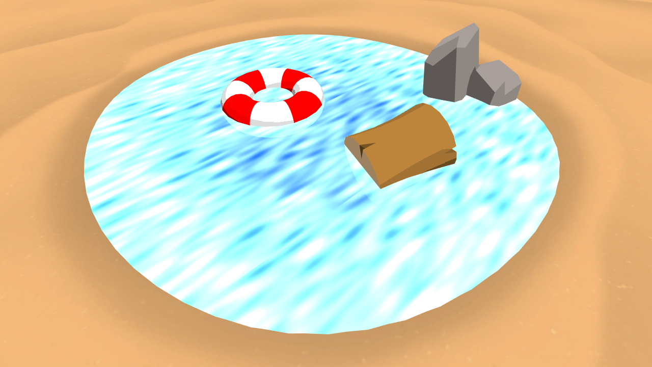
2. Waves
Next, we’ll add waves to the surface using a
noise texture
. As well, we’ll control the visibility of the waves using the depth of our water—this way, we can make the waves very visible at shallow depths to create a shoreline effect.
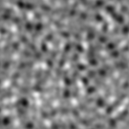
Perlin noise
, a type of noise. Perlin noise is pseudo-random, and is useful for adding variation to textures to avoid the appearance of unnatural repetition.
2.1 Using noise
While it’s possible to generate noise procedurally, for simplicity we’re going to just use a texture. Add the following code to set up our shader to take in a new texture property.
// As a new property in Properties.
_SurfaceNoise("Surface Noise", 2D) = "white" {}

…

// Add in the appdata struct.
float4 uv : TEXCOORD0;

…

// Add in the v2f struct.
float2 noiseUV : TEXCOORD0;

…

// Above the vertex shader.
sampler2D _SurfaceNoise;
float4 _SurfaceNoise_ST;

…

// Inside the vertex shader.
o.noiseUV = TRANSFORM_TEX(v.uv, _SurfaceNoise);
That’s a lot of code, but nothing in there is too exotic. We declare a new texture property and its matching
sampler2D
in the shader. Immediately below the
sampler2D
we declare another variable, a
float4
—Unity automatically populates this value with the
tiling
and
offset
data associated with the texture of the same name. Finally, UV data is declared in
appdata
and passed from the vertex shader to the fragment shader in the
v2f
struct.
What does TRANSFORM_TEX do? Why can’t we just pass the UV directly into fragment shader?
In the Unity editor, assign the
PerlinNoise
texture to the
Surface Noise
slot, and set the
Y
tiling to 4. Back in the shader, we will sample the noise texture and combine it with our surface color to render waves. Add the following at the end of the fragment shader.
float surfaceNoiseSample = tex2D(_SurfaceNoise, i.noiseUV).r;return waterColor + surfaceNoiseSample;
This vaguely resembles waves, but it’s too smooth and has far too much variation in brightness to match the toon style we’re going for. We will apply a cutoff threshold to get a more binary look.
// Add as a new property. _SurfaceNoiseCutoff("Surface Noise Cutoff", Range(0, 1)) = 0.777 … // Matching property variable. float _SurfaceNoiseCutoff; … // Add in the fragment shader, just after sampling the noise texture. float surfaceNoise = surfaceNoiseSample > _SurfaceNoiseCutoff ? 1 : 0;return waterColor + surfaceNoise;
That looks much better. Any values darker than the cutoff threshold are simply ignored, while any values above are drawn completely white.
2.2 Shoreline foam
We’d like the waves’ intensity to increase near the shoreline or where objects intersect the surface of the water, to create a
foam effect
. We’ll achieve this effect by modulating the noise cutoff threshold based off the water depth.
// Control for what depth the shoreline is visible. _FoamDistance("Foam Distance", Float) = 0.4 … // Matching variable. float _FoamDistance; … // Add in the fragment shader, above the existing surfaceNoise declaration. float foamDepthDifference01 = saturate(depthDifference / _FoamDistance); float surfaceNoiseCutoff = foamDepthDifference01 * _SurfaceNoiseCutoff; float surfaceNoise = surfaceNoiseSample >surfaceNoiseCutoff? 1 : 0;
The foam looks great near the shoreline, but it’s pretty thin around the object intersections; we’ll address this later.
2.3 Animation
Static water isn’t very interesting—let’s add some
motion
and
distortion
to the waves, starting with motion. We’ll achieve this by offsetting the UVs we use to sample the noise texture.
// Property to control scroll speed, in UVs per second. _SurfaceNoiseScroll("Surface Noise Scroll Amount", Vector) = (0.03, 0.03, 0, 0) … float2 _SurfaceNoiseScroll; … // Add in the fragment shader, above the existing surfaceNoiseSample line. float2 noiseUV = float2(i.noiseUV.x + _Time.y * _SurfaceNoiseScroll.x, i.noiseUV.y + _Time.y * _SurfaceNoiseScroll.y); float surfaceNoiseSample = tex2D(_SurfaceNoise,noiseUV).r;
Right now the scrolling feels like a sheet of paper being pulled across the surface. We’ll add more movement using a
distortion texture
. This distortion texture will be similar to a
Normal map
, except with only two channels (red and green) instead of three.
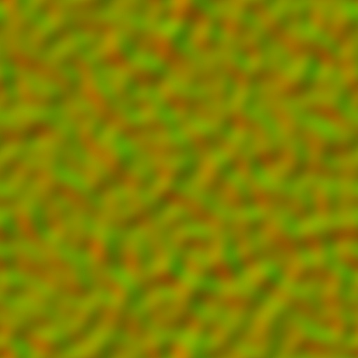
We’ll interpret these two channels as vectors on a 2 dimensional plane, and use them to pull around our noise texture’s UVs.
// Two channel distortion texture.
_SurfaceDistortion("Surface Distortion", 2D) = "white" {}
// Control to multiply the strength of the distortion.
_SurfaceDistortionAmount("Surface Distortion Amount", Range(0, 1)) = 0.27

…

// Matching variables.
sampler2D _SurfaceDistortion;
float4 _SurfaceDistortion_ST;

float _SurfaceDistortionAmount;

…

// New data in v2f.
float2 distortUV : TEXCOORD1;

…

// Add to the vertex shader.
o.distortUV = TRANSFORM_TEX(v.uv, _SurfaceDistortion);

…

// Add the fragment shader, just above the current noiseUV declaration line.
float2 distortSample = (tex2D(_SurfaceDistortion, i.distortUV).xy * 2 - 1) * _SurfaceDistortionAmount;

float2 noiseUV = float2((i.noiseUV.x + _Time.y * _SurfaceNoiseScroll.x) + distortSample.x, (i.noiseUV.y + _Time.y * _SurfaceNoiseScroll.y) + distortSample.y);
We declare our new texture property and add a new UV set as normal. In the fragment shader, we sample the distortion texture—but before adding it to our noiseUV, we multiply it by 2 and subtract 1; as a texture, the
x
and
y
values (red and green, respectively) are in the 0…1 range. As a two dimensional vector, however, we want it to be in the -1…1 range. The arithmetic above performs this operation.
What’s the difference between accessing a float4’s rgba components versus xyzw?
3. Consistent size foam
The foam right now looks great near the shoreline, but is barely visible around the edges of the floating objects. This is because the depth between the shore and the water is quite small, while the depth (from the camera’s point of view) between the water and the underwater objects is comparatively larger. Increasing the
_FoamDistance
to about 0.4 fixes this, but makes the shoreline exceedingly large.
Increasing the foam distance makes the foam around the objects look correct, but is far too strong for the shoreline.
Instead, we’ll create a solution that varies the depth that foam is rendered based off the
angle
of the surface below the water. That way, nearly vertical surfaces (like the rocks) can get foam deeper than very flat objects, like shoreline. Ideally, by modulating the foam amount like this they will visually have consistent foam in the final image.
3.1 Rendering the normals buffer
Our goal is to modulate the foam depth value (
_FoamDistance
in our shader) based on the angle between the normal of the water’s surface and the normal of the object between it. To do this, we’ll need to have access to a
normals buffer
.
Similar to the depth buffer, this will be a screen-size texture usuable within our shader. However, instead of storing the depth of each pixel, it’ll store its
normal
.
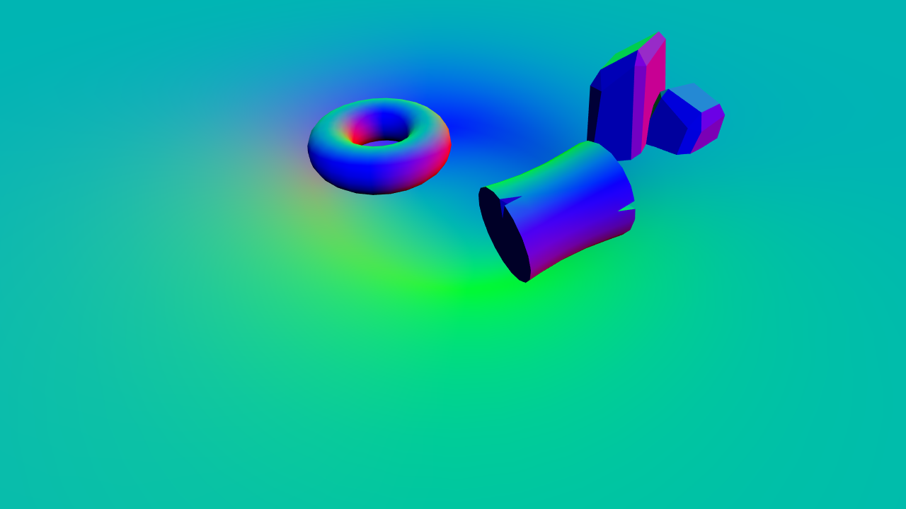
View space normals texture for the beach scene, excluding the water.
View space normals
are the normals of the scene relative to the camera’s view.
Unity does have the built-in functionality to render out the normals buffer by using the
DepthNormals
depth texture mode. This packs the depth and normals buffer into a single texture (two channels for each buffer). Unfortunately, this results in the depth buffer having too little precision for our purposes; instead, we’ll manually render out the normals to a separate texture. The starter project already contains a C# script to do this,
NormalsReplacementShader.cs
.
This script creates a camera at the same position and rotation as the main camera, except it renders the scene with a
Replacement Shader
. As well, instead of rendering the scene to the screen, it stores the output to a global shader texture named
_CameraNormalsTexture
. This texture, like the
_CameraDepthTexture
we used above, is available to all shaders.
Apply this script to the
Camera
object in the scene. As well, drag the
HiddenNormalsTexture
shader (in the
Shaders
folder) into the
Normals shader
slot. This shader is fairly simple; it outputs the
view space
normal of the object. View space normals are the normals of the object, relative to the camera’s view.
If you run the scene now, you’ll see that a new camera,
Normals camera
is automatically spawned as a child to the main camera. If you select this object, you can see in the normals being rendered in the
Camera preview
. Alternatively, double click the texture in the
Target texture
slot of the camera to see a larger preview.
3.2 Comparing view space normals
We’ll need to calculate the view space normal of the water surface before we can compare it to the normal rendered out to the texture. We can do this in the vertex shader and pass it through to the fragment shader.
// Add to appdata.
float3 normal : NORMAL;

…

// Add to v2f.
float3 viewNormal : NORMAL;

…

// Add to the vertex shader.
o.viewNormal = COMPUTE_VIEW_NORMAL;
With the view normal available in the fragment shader, we can compare it to the normal of the object beneath the water’s surface. We’ll sample the normals buffer in the same way we sampled the depth buffer.
// As this refers to a global shader variable, it does not get declared in the Properties.
sampler2D _CameraNormalsTexture;

…

// Add to the fragment shader, just above the existing foamDepthDifference01 line.
float3 existingNormal = tex2Dproj(_CameraNormalsTexture, UNITY_PROJ_COORD(i.screenPosition));
We now have the view normal of the water’s surface and the object behind it. We will compare the two using the
Dot Product
.
The dot product takes in two vectors (of any length) and returns a single number. When the vectors are parallel in the same direction and are
unit vectors
(vectors of length 1), this number is 1. When they are perpendicular, it returns 0. As you move a vector away from parallel—towards perpendicular—the dot product result will move from 1 to 0
non-linearly
. Note that when the angle between the vectors is
greater than 90
, the dot product will be negative.
// Add to the fragment shader, below the line sampling the normals texture.
float3 normalDot = saturate(dot(existingNormal, i.viewNormal));
We’ll use the result of the dot product to control the foam amount. When the dot product is large (near 1), we’ll use a lower foam threshold than when it is small (near 0).
// Replace the _FoamDistance property with the following two properties. _FoamMaxDistance("Foam Maximum Distance", Float) = 0.4 _FoamMinDistance("Foam Minimum Distance", Float) = 0.04 … // Replace the _FoamDistance variable with the following two variables. float _FoamMaxDistance; float _FoamMinDistance; … // Add to the fragment shader, above the existing foamDepthDifference01 line. float foamDistance = lerp(_FoamMaxDistance, _FoamMinDistance, normalDot); float foamDepthDifference01 = saturate(depthDifference /foamDistance);
By saturating the dot product result, we get our value in the 0…1 range, making it easy to pass into the
lerp
function, same as we did for interpolating the color of the water.
4. Transparency
Right now, the water is completely opaque. Although coloring by depth does give the illusion of transparency, the texture of the sand does not at all show through the water. This might actually be desirable for certain kinds of scenes—if you’re modelling ocean water, it would make sense for it to be rendered as opaque, since it tends to appear that way due to its immense depth. However, for our little pond scene we are going to add some transparency in to reflect the shallow nature of the water.
// Add just inside the SubShader, below its opening curly brace.
Tags
{
	"Queue" = "Transparent"
}
This tells Unity to render objects with this shader after all objects in the
“Geometry”
queue have been rendered; this queue is usually where opaque objects are drawn. This way, we can overlay our transparent water on top of all the opaque objects and blend them together. You can read more about rendering order and queues
here
.
// Add inside the Pass, just above the CGPROGRAM's start.
Blend SrcAlpha OneMinusSrcAlpha
ZWrite Off
The
Blend
line dictates how that blending should occur. We’re using a blending algorithm often referred to as
normal blending
, and is similar to how software like Photoshop blends two layers.
After that we have
ZWrite Off
. This prevents our object from being written into the depth buffer; if it
was
written into the depth buffer, it would
completely
occlude objects behind it, instead of only partially obscuring them.
![]()
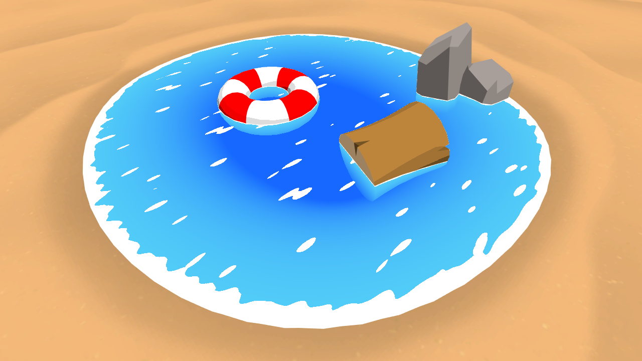
5. Improved blending
Our water just about matches the final image. Next, we’ll add a new property to control the color of the water foam. Although white looks great for this scene, different types of surfaces may require different colored foam.
_FoamColor("Foam Color", Color) = (1,1,1,1) … float4 _FoamColor; … // Add inside the fragment shader, just below the line declaring surfaceNoise. float4 surfaceNoiseColor = _FoamColor * surfaceNoise; return waterColor +surfaceNoiseColor;
This allows us to modify the color of the foam, but if you play with the
_FoamColor
variable in the scene, you’ll see that it gives mixed results. Red foam comes out pink, and completely black foam just leaves a light blue highlight in its place. This is because we are performing
additive blending
on the two colors used to generate our final value.
Modfying the color of the foam yields mixed results, with red foam turning pink and black foam light blue.
As the name implies, additive blending is the result of adding two colors together, creating a brighter result. This is great for objects that emit light, like sparks, explosions or lightning. We are want to blend the foam with the water surface—neither of these emit light, and the result should not be brighter; additive blending is not the right fit for this task.
Instead, we’ll blend the two colors together using the same algorithm Unity is using to blend our shader with the background, which we referred to above as
normal blending
. If we revisit the following line, we can take a look at how this blending works.
Blend SrcAlpha OneMinusSrcAlpha
Blend
, when provided with two parameters, works by multiplying the the output of the shader by the first value (
SrcAlpha
, or the alpha of the shader output), multiplying the on screen color by the second value (
OneMinusSrcAlpha
or 1 – alpha of the output), and then adding the two together for the final color.
This article by Unity
explains it in further detail.
We will replicate this as a function in our
CGPROGRAM
. Add the following above the
appdata
declaration.
float4 alphaBlend(float4 top, float4 bottom)
{
	float3 color = (top.rgb * top.a) + (bottom.rgb * (1 - top.a));
	float alpha = top.a + bottom.a * (1 - top.a);

	return float4(color, alpha);
}
The first line performs the blend operation described above. Because we want our final output to maintain transparency, we also perform the blend on the alpha channel of the colors. We will use this function to blend our final output.
// Place in the fragment shader, replacing the code in its place.float4 surfaceNoiseColor = _FoamColor;surfaceNoiseColor.a *= surfaceNoise;return alphaBlend(surfaceNoiseColor, waterColor);
Note that we only multiply the alpha of the foam now, instead of the entire color.
6. Anti-aliasing
We will make one final improvement before completing the shader. If you look closely at the foam, you’ll notice the edges are fairly jagged. This is the result of the binary way we perform the cutoff on our noise texture; every pixel either has full alpha, or none at all. Instead, we’ll smoothly blend the alpha from zero to one, using the
smoothstep
function.
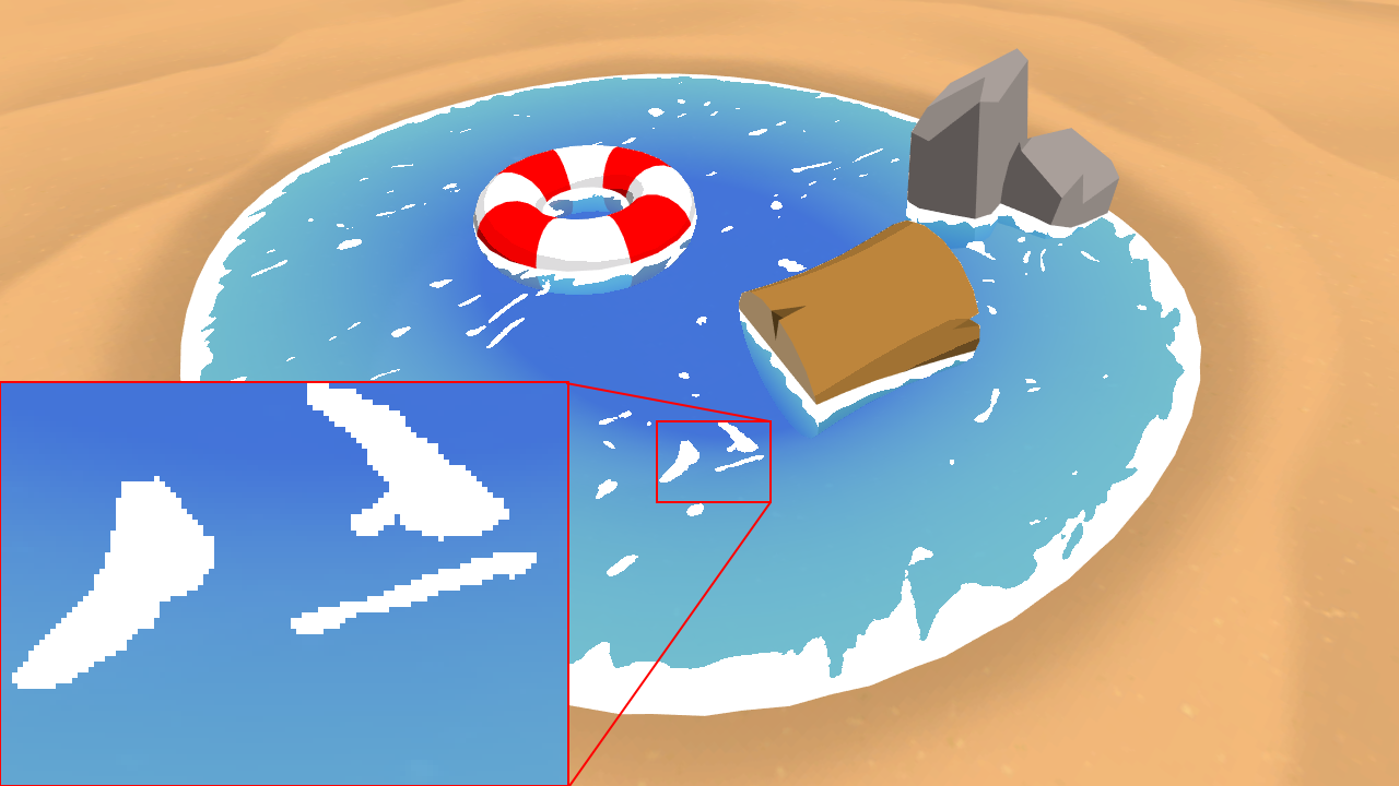
Jagged edges where the foam meets the water. To get a clearer view, open this image full-screen in a new tab.
smoothstep
is somewhat similar to
lerp
. It takes in three values: a
lower bound
, an
upper bound
and a value expected to be between these two bounds.
smoothstep
returns a value between 0 and 1 based on how far this third value is between the bounds. (If it is outside the lower or upper bound,
smoothstep
returns a 0 or 1, respectively).
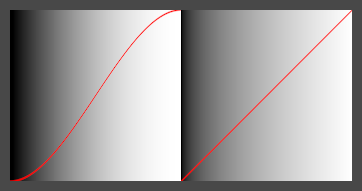
Comparison between
smoothstep
(left) and
lerp
(right). The values are mapped to the greyscale background, as well as the curves in red.
Unlike
lerp
,
smoothstep
is not linear: as the value moves from 0 to 0.5, it accelerates, and as it moves from 0.5 to 1, it decelerates. This makes it ideal for smoothly blending values, which is how we’ll use it below.
// Insert just after the CGPROGRAM begins. #define SMOOTHSTEP_AA 0.01 …float surfaceNoise = smoothstep(surfaceNoiseCutoff - SMOOTHSTEP_AA, surfaceNoiseCutoff + SMOOTHSTEP_AA, surfaceNoiseSample);
The lower and upper bounds we define (the first two parameters of the function) are quite close—they’re just far enough apart to add some smoothing to the edges. When
surfaceNoiseSample
is outside of these bounds, it will return 0 or 1, just like before.
Conclusion
The techniques learned here form the basis for a wide variety of graphical effects. The depth buffer can be used to achieve any kind of distance-based effect, like fog, or a scanner sweep. The normals buffer is used in
deferred shading
, where surfaces are lit
after
all rendering is done as a post process step. Distortion and noise have nearly unlimited applications, and can be used to modify the geometry of meshes, similar to how
heightmaps work
. It’s worth experimenting with the settings of the shader to see what can be achieved with it.
Leave me a message
Send me some feedback about the tutorial in the form below. I’ll get back to you as soon as I can! You can alternatively message me through
Twitter
or
Reddit
.
EmailMessageSend message