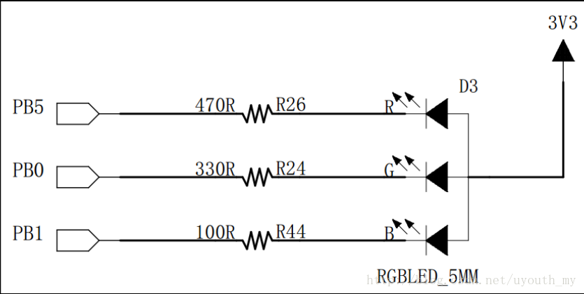
LED灯连接到STM32的GPIO引脚,可以通过控制低电平(0)点亮,高电平(1)熄灭。
编程要点
1).使能GPIO端口时钟
2).初始化GPIO目标引脚为推挽输出模式
3).编写简单的测试程序,控制GPIO引脚输出高、低电平
代码分析
1. LED灯引脚宏定义
将与硬件相关的部分使用宏来封装,这些定义存储在“led.h”文件中。
//R-红色
#define LED1_GPIO_PORT GPIOB
#define LED1_GPIO_CLK RCC_APB2Periph_GPIOB
#define LED1_GPIO_PIN GPIO_Pin_5
//G-绿色
#define LED2_GPIO_PORT GPIOB
#define LED2_GPIO_CLK RCC_APB2Periph_GPIOB
#define LED2_GPIO_PIN GPIO_Pin_0
// B-蓝色
#define LED3_GPIO_PORT GPIOB
#define LED3_GPIO_CLK RCC_APB2Periph_GPIOB
#define LED3_GPIO_PIN GPIO_Pin_1
以上是用代码把控制LED的GPIO端口、引脚以及GPIO端口时钟封装起来。
注:
GPIO 时钟宏“RCC_APB2Periph_GPIOB”是 STM32 标准库定义的 GPIO 端口时钟相关的宏,是用于指示寄存器位的。
一共32bit,4bit控制一个位,如果使能AFIO时钟即是((uint32_t)0x00000001),如果使能GPIOB时钟即是((uint32_t)0x00000008)。这也就是控制寄存器的位,用宏定义封装即是
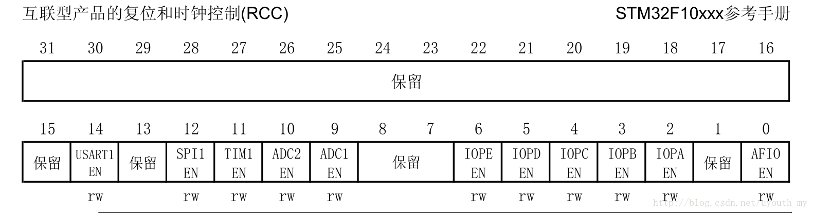
#define RCC_APB2Periph_AFIO              ((uint32_t)0x00000001)
#define RCC_APB2Periph_GPIOA             ((uint32_t)0x00000004)
#define RCC_APB2Periph_GPIOB             ((uint32_t)0x00000008)
#define RCC_APB2Periph_GPIOC             ((uint32_t)0x00000010)
#define RCC_APB2Periph_GPIOD             ((uint32_t)0x00000020)
#define RCC_APB2Periph_GPIOE             ((uint32_t)0x00000040)
#define RCC_APB2Periph_GPIOF             ((uint32_t)0x00000080)
#define RCC_APB2Periph_GPIOG             ((uint32_t)0x00000100)
#define RCC_APB2Periph_ADC1              ((uint32_t)0x00000200)
#define RCC_APB2Periph_ADC2              ((uint32_t)0x00000400)
#define RCC_APB2Periph_TIM1              ((uint32_t)0x00000800)
#define
版权声明:本文为uyouth_my原创文章,遵循 CC 4.0 BY-SA 版权协议,转载请附上原文出处链接和本声明。