目录
第一部分、前言
1、TOF10120激光测距模块的基本知识
模块最佳距离测量范围:
10cm~180cm
。这里的范围
是指
这个模块在这个距离范围内测到的数据都非常准确,
而不是指
我只能测量这个范围的距离,其它距离测量不了,超过这个距离范围,误差会大一点而已。
工作电压:
3.3V~5V
都可以,不容易烧。
通讯协议:
这个模块支持
串口协议
和
IIC协议
,串口协议默认波特率
9600
,但是我这个工程是利用IIC协议调试的,因为单片机的串口毕竟有限。
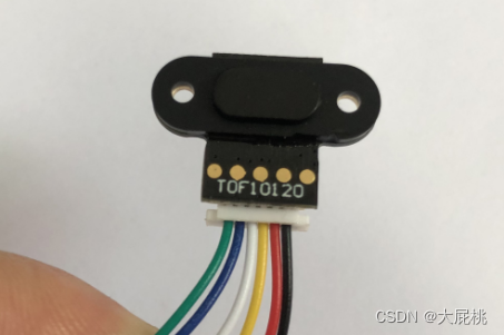
2、TOF的引脚
下图是我模块的样子,从左到右的引脚对应如下表格
|
绿线 |
SCL |
|
蓝线 |
SDA |
|
白线 |
TXD |
|
黄线 |
RXD |
|
红线 |
VCC |
|
黑线 |
GND |
3、与单片机的接线
本次调试利用的是
IIC协议
,没有用到串口,因此
白线
和
黄线
就可以不要了,后来我直接把这根线直接给剪掉了?。
IIC协议是模拟出来,
绿线
SCL —— PB12;
蓝线
SDA —— PB13,
注意:
单片机用的核心板C8T6。
第二部分、工程代码
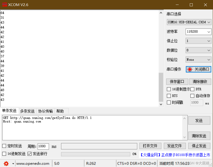
1、代码功能描述
串口一不断将距离数据打印在电脑的串口助手,每隔1s打印一次,LED闪烁。
注意:
这里得到的距离数据已经是模块内部滤波后的数据,这种得到的数值比较平滑。如果想要得到实时距离,需要更改寄存器的值,这里请自行参考TOF10120的技术手册。
2、tof.h文件
#ifndef __TOF_H
#define __TOF_H
#include "sys.h"

//   绿线SCL —— PB12
//   蓝线SDA —— PB13


//管脚宏定义
#define I2C_SCL_PIN          	GPIO_Pin_12
#define I2C_SCL_PORT    		GPIOB
#define I2C_SCL_CLK       		RCC_APB2Periph_GPIOB

#define I2C_SDA_PIN             GPIO_Pin_13
#define I2C_SDA_PORT          	GPIOB
#define I2C_SDA_CLK           	RCC_APB2Periph_GPIOB


//IO操作函数
#define USERI2C_SCL_1   	GPIO_SetBits(I2C_SCL_PORT, I2C_SCL_PIN)
#define USERI2C_SCL_0   	GPIO_ResetBits(I2C_SCL_PORT, I2C_SCL_PIN)
#define USERI2C_SDA_1   	GPIO_SetBits(I2C_SDA_PORT, I2C_SDA_PIN)
#define USERI2C_SDA_0   	GPIO_ResetBits(I2C_SDA_PORT, I2C_SDA_PIN)

#define USERI2C_READ_SDA  (GPIO_ReadInputDataBit(I2C_SDA_PORT, I2C_SDA_PIN))

#define I2C_DEVID    			164//0XA4


//函数声明
void UserI2c_Start(void);

void UserI2c_Init(void);

unsigned char SensorWritenByte(unsigned char Devid, unsigned char *TXBuff, unsigned char SubAdd, unsigned char Size);
unsigned char SensorReadnByte(unsigned char Devid, unsigned char *RXBuff, unsigned char SubAdd, unsigned char Size);


#endif
3、tof.c文件
#include "tof.h"
#include "delay.h"

#include "usart.h"

//变量定义
unsigned char devid;
unsigned int i2cread_interval;
unsigned char dirt_send_flag;
unsigned char dirt_detection_flag;
unsigned short int length_val;
unsigned short int length_aveval;


/*******************************************************************************
* Function Name  : UserI2c_Start
* Description    : sck stable in H,sda falling edge
* Input          : None
* Output         : None
* Return         : None
*******************************************************************************/
void UserI2c_Start(void)
{
    USERI2C_SDA_1;
    delay_us(5);
    USERI2C_SCL_1;
    delay_us(5);
    USERI2C_SDA_0;  //START:when CLK is high,DATA change form high to low
    delay_us(5);
    USERI2C_SCL_0;  //钳住I2C总线,准备发送或接收数据
    delay_us(30);  //加30uS延时
}


/*******************************************************************************
* Function Name  : UserI2c_Stop
* Description    : sck stable in H,sda rising edge
* Input          : None
* Output         : None
* Return         : None
*******************************************************************************/
void UserI2c_Stop(void)
{
    USERI2C_SCL_0;
    USERI2C_SDA_0;//STOP:when CLK is high DATA change form low to high
    delay_us(5);
    USERI2C_SCL_1;
    delay_us(5);
    USERI2C_SDA_1;  //发送I2C总线结束信号
    delay_us(5);

    delay_us(30);   //加30uS延时
}

/*******************************************************************************
* Function Name  : UserI2c_Wait_Ack
* Description    : the 9th clock pulse period wait ack
* Input          : None
* Output         : None
* Return         : =0有ack
*								 : =1无ack
*******************************************************************************/
unsigned char UserI2c_Wait_Ack(void)
{
    GPIO_InitTypeDef GPIO_InitStructure;
    unsigned short int ucErrTime = 0;
    unsigned char RetValue;

    //SDA设置为输入
    GPIO_InitStructure.GPIO_Pin = I2C_SDA_PIN;
    GPIO_InitStructure.GPIO_Mode = GPIO_Mode_IPU ;   //上拉输入
    GPIO_Init(I2C_SDA_PORT, &GPIO_InitStructure);

    USERI2C_SCL_0;
    delay_us(5);
    USERI2C_SCL_1;

    ucErrTime = 10000;

    while( ucErrTime-- > 0 )
    {
        if(USERI2C_READ_SDA )
        {
            RetValue = 0;
        }
        else
        {
            RetValue = 1;
            break;
        }
    }

    delay_us(1);
    USERI2C_SCL_0;//时钟输出0

    //SDA线输出
    GPIO_InitStructure.GPIO_Pin = I2C_SDA_PIN;
    GPIO_InitStructure.GPIO_Mode = GPIO_Mode_Out_PP ;   //推挽输出
    GPIO_InitStructure.GPIO_Speed = GPIO_Speed_50MHz;   //配置IO的输出速度为50MHz,高低电平状态最高切换频率
    GPIO_Init(I2C_SDA_PORT, &GPIO_InitStructure);

    USERI2C_SDA_0;
    delay_us(30);     //加30uS延时
    return RetValue;
}


/*******************************************************************************
* Function Name  : useri2c_ack
* Description    : the 9th clock pulse period, the receiver pulls sda low to
* 							 : acknowledge the receipt of the eight data bits.
* Input          : None
* Output         : None
* Return         : None
*******************************************************************************/
void useri2c_ack(void)
{
    USERI2C_SCL_0;
    USERI2C_SDA_0;
    delay_us(5);
    USERI2C_SCL_1;
    delay_us(5);
    USERI2C_SCL_0;
    delay_us(30);     //加30uS延时
}

/*******************************************************************************
* Function Name  : useri2c_nack
* Description    : no acknowledge the receipt of the eight data bits.
* Input          : None
* Output         : None
* Return         : None
*******************************************************************************/
void useri2c_nack(void)
{
    USERI2C_SCL_0;
    USERI2C_SDA_1;
    delay_us(5);
    USERI2C_SCL_1;
    delay_us(5);
    USERI2C_SCL_0;
    delay_us(30);     //加30uS延时
}

/*******************************************************************************
* Function Name  : UserI2c_Send_Byte
* Description    : write one data to i2c bus
* Input          : txd-data
* Output         : None
* Return         : None
*******************************************************************************/
void UserI2c_Send_Byte(unsigned char txd)
{
    unsigned char t;

    USERI2C_SCL_0;//拉低时钟开始数据传输
    delay_us(5);

    for(t = 0; t < 8; t++)
    {
        if((txd & 0x80) >> 0)
            USERI2C_SDA_1;
        else
            USERI2C_SDA_0;

        txd <<= 1;
        delay_us(5);
        USERI2C_SCL_1;
        delay_us(5);
        USERI2C_SCL_0;
    }
}


/*******************************************************************************
* Function Name  : UserI2c_Read_Byte
* Description    : read one data from i2c bus
* Input          : None
* Output         : None
* Return         : receoved data
*******************************************************************************/
unsigned char UserI2c_Read_Byte(void)
{
    GPIO_InitTypeDef GPIO_InitStructure;
    unsigned char i, receive = 0;

    //SDA设置为输入
    GPIO_InitStructure.GPIO_Pin = I2C_SDA_PIN;
    GPIO_InitStructure.GPIO_Mode = GPIO_Mode_IPU ;   //上拉输入
    GPIO_Init(I2C_SDA_PORT, &GPIO_InitStructure);

    USERI2C_SDA_1;
    USERI2C_SCL_0;
    delay_us(30);

    for(i = 0; i < 8; i++ )
    {
        receive <<= 1;
        USERI2C_SCL_1;
        delay_us(5);

        if(USERI2C_READ_SDA)
            receive++;

        USERI2C_SCL_0;
        delay_us(5);
    }

    USERI2C_SCL_0;

    //SDA线输出
    GPIO_InitStructure.GPIO_Pin = I2C_SDA_PIN;
    GPIO_InitStructure.GPIO_Mode = GPIO_Mode_Out_PP ;   //推挽输出
    GPIO_InitStructure.GPIO_Speed = GPIO_Speed_50MHz;
    GPIO_Init(I2C_SDA_PORT, &GPIO_InitStructure);

    return receive;
}
/**************************************************************************************************************************/

/*******************************************************************************
* Function Name  :SensorWritenByte
* Description    :  Sensor read api.
* Input          : devid-设备i2c地址
*                : *TXBuff-the address of the buffer which to write.
*                : SubAdd-the address read to
*                : Size-the buffer size
* Output         : None
* Return         : None
*******************************************************************************/
unsigned char SensorWritenByte(unsigned char Devid, unsigned char *TXBuff, unsigned char SubAdd, unsigned char Size)
{
    unsigned char i = 0;

    UserI2c_Start();

    UserI2c_Send_Byte( Devid | 0x00 );

    if( 0 == UserI2c_Wait_Ack() )
    {
        UserI2c_Stop();
        return 0;
    }

    UserI2c_Send_Byte( SubAdd & 0xff );

    if( 0 == UserI2c_Wait_Ack() )
    {
        UserI2c_Stop();
        return 0;
    }

    for ( i = 0; i < Size; i++)
    {
        UserI2c_Send_Byte( TXBuff[Size - i - 1] );

        if( 0 == UserI2c_Wait_Ack() )
        {
            UserI2c_Stop();
            return 0;
        }
    }

    UserI2c_Stop();

    return 1;
}


/*******************************************************************************
* Function Name  : SensorReadnByte
* Description    :  Sensor read api.
* Input          : devid-设备i2c地址
*                : *RXBuff-the address of the buffer which stores read content.
*                : SubAdd-the address read from
*                : Size-the buffer size
* Output         : None
* Return         : None
*******************************************************************************/
unsigned char SensorReadnByte(unsigned char Devid, unsigned char *RXBuff, unsigned char SubAdd, unsigned char Size)
{
    unsigned char i = 0;

    UserI2c_Start();

//    UserI2c_Send_Byte( Devid | 0x00 ); //实时距离地址
		UserI2c_Send_Byte( Devid | 0x04 );   //滤波距离地址
    if( 0 == UserI2c_Wait_Ack() )
    {
        UserI2c_Stop();
        return 0;
    }

    UserI2c_Send_Byte( SubAdd & 0xff );

    if( 0 == UserI2c_Wait_Ack() )
    {
        UserI2c_Stop();
        return 0;
    }

    UserI2c_Stop();

    UserI2c_Start();
    //UserI2c_Send_Byte( Devid | 0x01 ); //实时距离地址
		UserI2c_Send_Byte( Devid | 0x05 );   //滤波距离地址


    if( 0 == UserI2c_Wait_Ack() )
    {
	//  UserI2c_Stop();
	//    return 0;
    }

    for ( i = 0; i < Size; i++)
    {

        RXBuff[Size - i - 1] = UserI2c_Read_Byte();

        if((i + 1) == Size)
            useri2c_nack();
        else
            useri2c_ack();

    }

    UserI2c_Stop();

    return 1;
}


/*******************************************************************************
* Function Name  : UserI2c_Init
* Description    : config i2c driver gpio
* Input          : None
* Output         : None
* Return         : None
*******************************************************************************/
void UserI2c_Init(void)
{
    GPIO_InitTypeDef GPIO_InitStructure;
    RCC_APB2PeriphClockCmd(	I2C_SCL_CLK, ENABLE );
    RCC_APB2PeriphClockCmd(	I2C_SDA_CLK, ENABLE );

    GPIO_InitStructure.GPIO_Pin = I2C_SCL_PIN;
    GPIO_InitStructure.GPIO_Mode = GPIO_Mode_Out_PP ;   //推挽输出
    GPIO_InitStructure.GPIO_Speed = GPIO_Speed_50MHz;
    GPIO_Init(I2C_SCL_PORT, &GPIO_InitStructure);

    GPIO_InitStructure.GPIO_Pin = I2C_SDA_PIN;
    GPIO_Init(I2C_SDA_PORT, &GPIO_InitStructure);


    GPIO_SetBits(I2C_SCL_PORT, I2C_SCL_PIN); 	//SCL 输出高
    GPIO_SetBits(I2C_SDA_PORT, I2C_SDA_PIN); 	//SDA 输出高
/************************/
/**配置TOF内部寄存器*****/
/**代码改于2022/6/1_dpt**/
/************************/
	devid=I2C_DEVID;       //设置I2C从机地址  默认164 0xA4

	dirt_send_flag=1;			 //=0串口主动发送 =1串口或者I2C被动读取
	SensorWritenByte(devid,(unsigned char *)&dirt_send_flag, 0x09, 1);      //0x09设置距离发送方式  1 主机去读取  0 模块发送
	delay_ms(100);

	dirt_detection_flag=0; //=0滤波值 =1实时值
	SensorWritenByte(devid,(unsigned char *)&dirt_detection_flag, 0x08, 1);  //0x08设置 距离数据模式   1 实时值 0滤波值
	delay_ms(100);

}

/************************END OF FILE*************************/
4、main.c文件
#include "sys.h"
#include "led.h"
#include "delay.h"
#include "usart.h"
#include "tof.h"

//变量定义
extern unsigned char devid;                      //I2C从机地址声明
extern unsigned short int length_aveval;  //用来存储长度数据

int main()
{
	NVIC_PriorityGroupConfig(NVIC_PriorityGroup_2);	//中断控制器分组设置
	delay_init();                                   //初始化很重要//用不了的函数一般都是没有初始化  TOF模拟IIC用到,所以放到前面
/*串口*/
	Usart1_Init(115200);
/*LED*/
	LED_Init();
/*Tof*/
  UserI2c_Init();	       //TOF模块初始化引脚,配置寄存器

	while(1)
	{
		LED0 = 0;
		delay_ms(500);
		LED0 = 1;
		delay_ms(500);

		SensorReadnByte(devid,(unsigned char *)&length_aveval, 0x04,2);//注意:这里我已更改为滤波距离
		printf("%d\r\n",length_aveval);
	}
}
第三部分、总结
1、TOF10120的数据参考手册
这是博主看的数据手册,我这里面的很多东西都是从数据手册搬运过来,手册链接:
TOF10120数据参考手册
(
无需积分下载
)。
2、完整的工程代码
这是博主的完整的代码,可以免费下载,但是你
是不是要点个赞,然后再下载??
STM32驱动TOF10120激光测距模块的完整代码
有问题的小伙伴现在可以进群询问啦,当然
我所有博客中涉及到的参考资料和工程
都在群文件里。之前也在博客中放过群号,但是那个时候没有时间,群里面的小伙伴发的消息我都没时间回复,所以就把群号给屏蔽了,现在读研了,有时间了。欢迎大家的加入。群聊目前处于起步阶段,哈哈哈哈哈???