Author:
HuaZhouqi
Department of Computer Science & Technology, Tongji University, Shanghai.
R-type
add
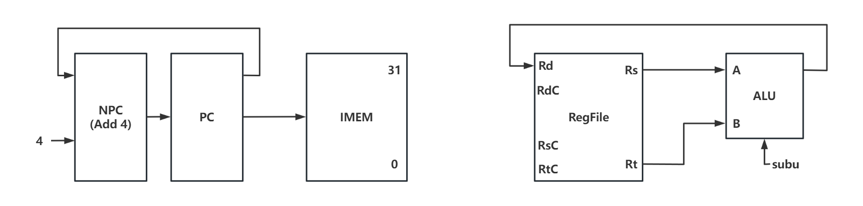
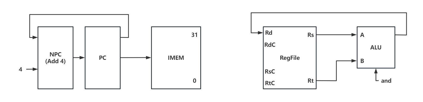
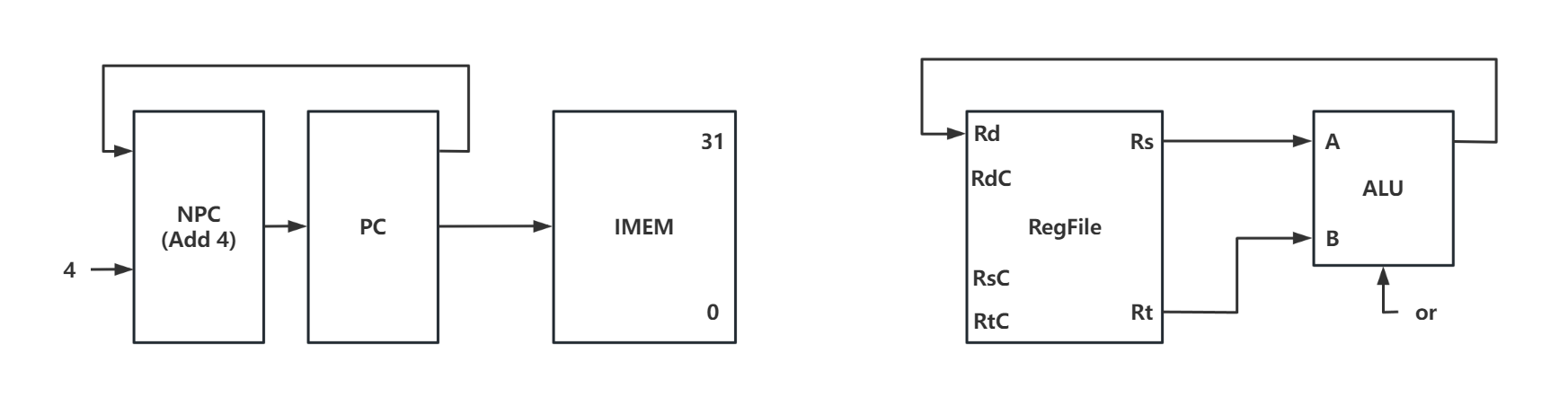
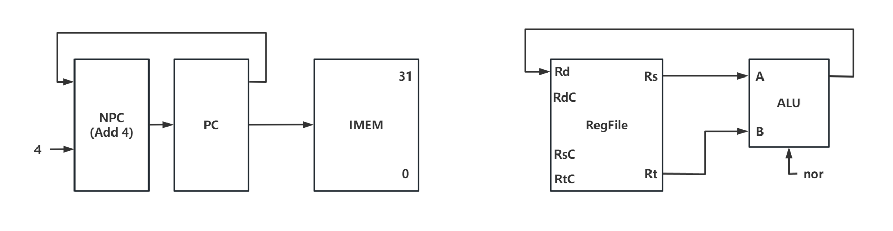
Design methodology:
- After non-jump instructions such as add being executed,
PC
(Program Counter) will point to the address of next instruction, which means a self-increment of 4. So, an independent pathway is necessary to complete this task.- Arithmetic operations such as add need the participant of
ALU
(Arithmetic&logical Unit). Rs as well as Rt stores the source operands of ALU, and the result will be sent to register Rd.- To differentiate different arithmetic operations (such as add / sub …etc ), a control signal will be sent to ALU.
Instructions
addu
/
sub
/
subu
/
and
/
or
/
xor
/
nor
are similar to
add
( while using the same register and pathways data being delivered, the only difference is category of the calculation of
ALU
)
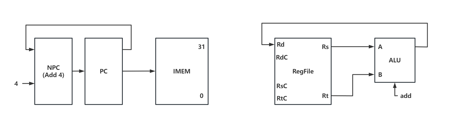
PC -> IMEM
PC + 4 -> NPC
NPC -> PC
Rs -> A
Rt -> B
RES -> Rd
addu
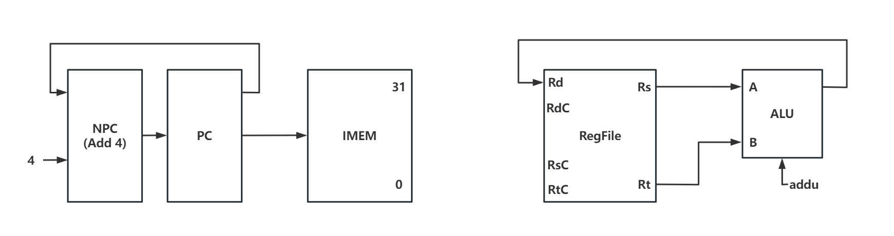
PC -> IMEM
PC + 4 -> NPC
NPC -> PC
Rs -> A
Rt -> B
RES -> Rd
sub
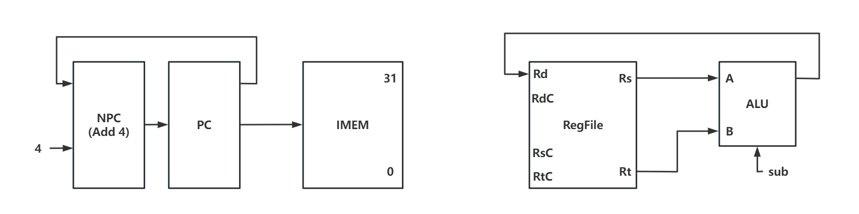
PC -> IMEM
PC + 4 -> NPC
NPC -> PC
Rs -> A
Rt -> B
RES -> Rd
subu
PC -> IMEM
PC + 4 -> NPC
NPC -> PC
Rs -> A
Rt -> B
RES -> Rd
and
PC -> IMEM
PC + 4 -> NPC
NPC -> PC
Rs -> A
Rt -> B
RES -> Rd
or
PC -> IMEM
PC + 4 -> NPC
NPC -> PC
Rs -> A
Rt -> B
RES -> Rd
xor
![[外链图片转存失败,源站可能有防盗链机制,建议将图片保存下来直接上传(img-ntkV00j8-1684844002282)(C:/Users/h1585/AppData/Roaming/Typora/typora-user-images/image-20230522100454721.png)]](https://img-blog.csdnimg.cn/c1b2b8b6d7bc4860a48110d34e6d1c6e.png)
PC -> IMEM
PC + 4 -> NPC
NPC -> PC
Rs -> A
Rt -> B
RES -> Rd
nor
PC -> IMEM
PC + 4 -> NPC
NPC -> PC
Rs -> A
Rt -> B
RES -> Rd
slt
Design methodology:
slt
instruction will return the boolean result of size comparison.Return 1 if the former is greater than the latter
Return 0 if the former is less than the latter
It can be understood as a composite instruction calculated using the sub instruction, or a brand new instruction simply using
ALU
to produce result.After non-jump instructions such as add being executed,
PC
(Program Counter) will point to the address of next instruction, which means a self-increment of 4. So, an independent pathway is necessary to complete this task. (Same as instructions above)Instructions
sltu
is similar to
slt
.
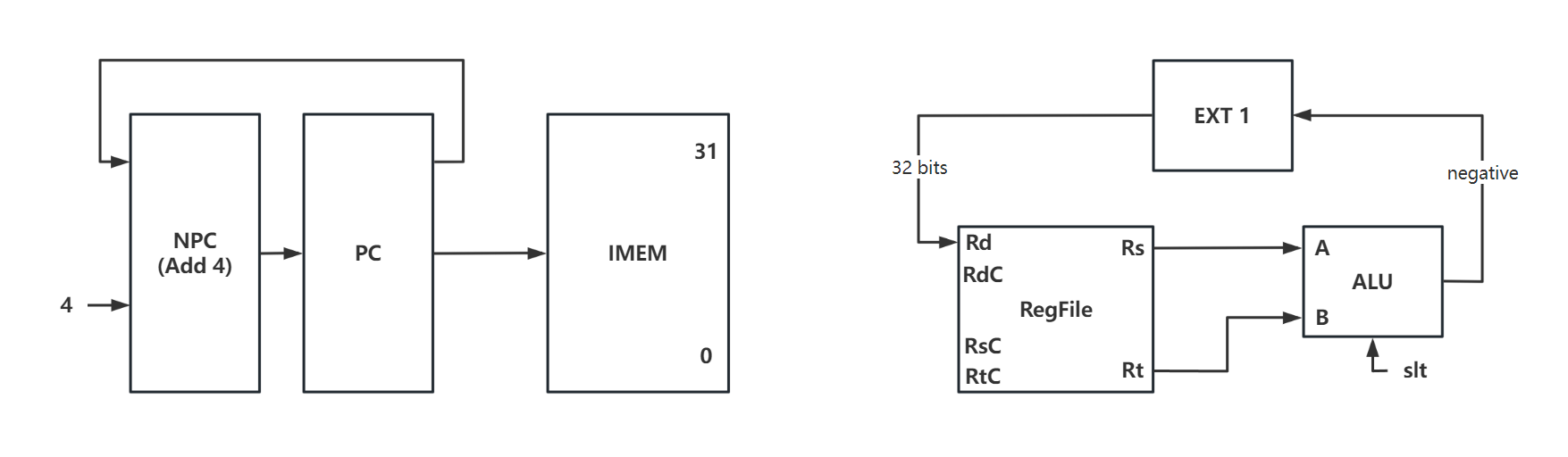
PC -> IMEM
PC + 4 -> NPC
NPC -> PC
Rs -> A
Rt -> B
SF -> EXT1
EXT1(out) -> Rd
Note that the size of register Rd is
32 bit
, so it’s necessary to expand
SF
results using
EXT1
to 32-bit. It’s same with instructions below
sltu
.
sltu
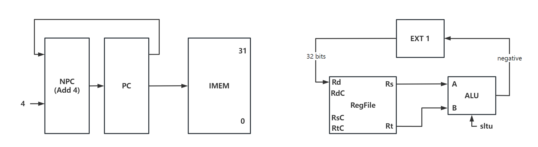
PC -> IMEM
PC + 4 -> NPC
NPC -> PC
Rs -> A
Rt -> B
SF -> EXT1
EXT1(out) -> Rd
sll
Design methodology:
sll
instruction will shift the operand to the left (
IMEM
) bits
Shamt
appears for the first time in instructions, dealing with immediate data (stored in IMEM) and carry out instruction truncation and unsigned extension.- After non-jump instructions such as add being executed,
PC
(Program Counter) will point to the address of next instruction, which means a self-increment of 4. So, an independent pathway is necessary to complete this task. (Same as instructions above)Instructions
srl
/
sra
are similar to
sll
, which all represent shift operations.
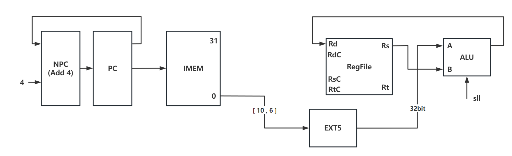
PC -> IMEM
PC + 4 -> NPC
NPC -> PC
IMEM[10:6] -> EXT5
EXT5_OUT -> A
Rt -> B
Res -> Rd
srl

PC -> IMEM
PC + 4 -> NPC
NPC -> PC
IMEM[10:6] -> EXT5
EXT5_OUT -> A
Rt -> B
Res -> Rd
sra
Note that
sra
performs arithmetic shift left and needs to complete symbol bits.
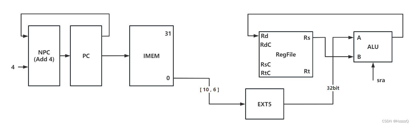
PC -> IMEM
PC + 4 -> NPC
NPC -> PC
IMEM[10:6] -> EXT5
EXT5_OUT -> A
Rt -> B
Res -> Rd
sllv
Different from
sll
or
srl
, both operands of
sllv
come from registers. (instead of immediate data)Instructions
srlv
/
srav
are similar to
sllv
, which all represent shift operations and fetch operands from registers.
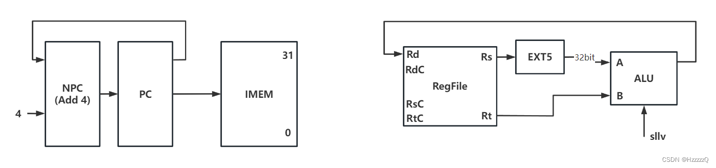
PC -> IMEM
PC + 4 -> NPC
NPC -> PC
Rs[4:0] -> EXT5
EXT5_OUT -> A
Rt -> B
Res -> Rd
srlv
![[外链图片转存失败,源站可能有防盗链机制,建议将图片保存下来直接上传(img-mtD9rPJA-1684844002285)(C:/Users/h1585/AppData/Roaming/Typora/typora-user-images/image-20230522103328646.png)]](https://img-blog.csdnimg.cn/85d7df3f651d4bfd8b9f57ba1da80605.png)
PC -> IMEM
PC + 4 -> NPC
NPC -> PC
Rs[4:0] -> EXT5
EXT5_OUT -> A
Rt -> B
Res -> Rd
srav
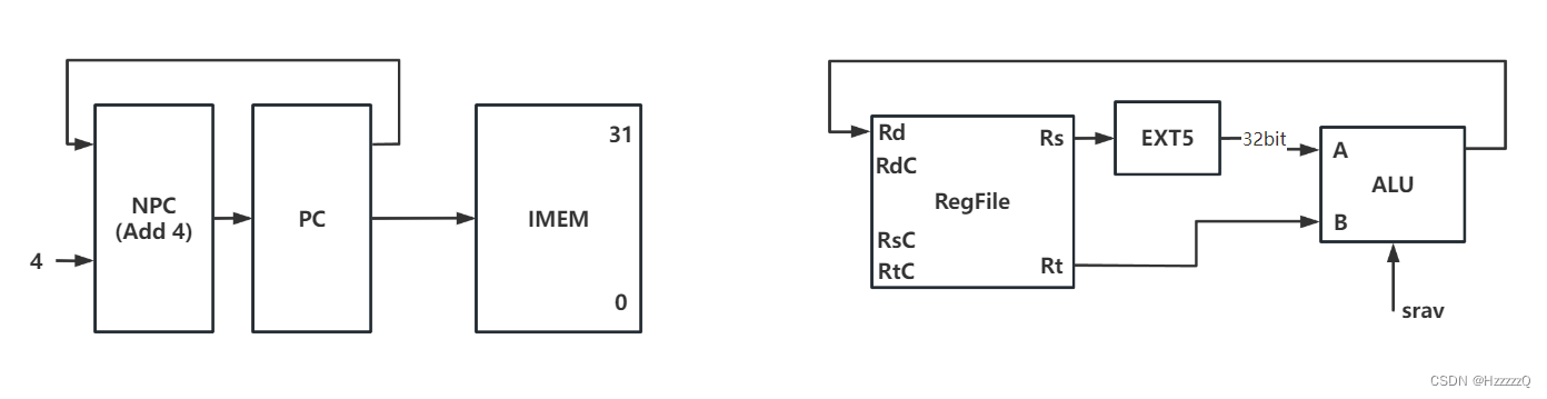
PC -> IMEM
PC + 4 -> NPC
NPC -> PC
Rs[4:0] -> EXT5
EXT5_OUT -> A
Rt -> B
Res -> Rd
jr
Design methodology:
- Unlike the previous R-type instructions,
jr
has the function of
PC jump
- Based on the data in the
register
to determine whether the PC needs to jump, so there is no need for ALU to participate.- To choose PC+4 or PC-JMP, a
MUX
is necessary.- After non-jump instructions such as add being executed,
PC
(Program Counter) will point to the address of next instruction, which means a self-increment of 4. So, an independent pathway is necessary to complete this task. (Same as instructions above)
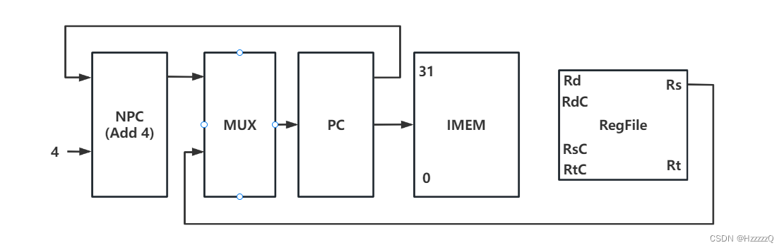
PC -> IMEM
Rs -> MUX
MUX_OUT -> PC
PC + 4 -> NPC
NPC -> MUX
I-type
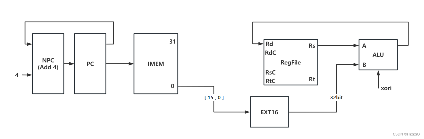
addi
Design methodology:
- Similar to
sll
,
addi
alse fetchs serval bits from
IMEM
and sends to
ALU
.- The function of
EXT16
is signed extension ( same with
addiu
/
slti
/
sltiu
)- After non-jump instructions such as add being executed,
PC
(Program Counter) will point to the address of next instruction, which means a self-increment of 4. So, an independent pathway is necessary to complete this task. (Same as instructions above)Instructions
addiu
/
andi
/
ori
/
xori
are similar to
addi
.

PC -> IMEM
PC + 4 -> NPC
NPC -> PC
IMEM[15:0] -> EXT16
EXT16_OUT -> B
Rs -> A
Res -> Rd
andi
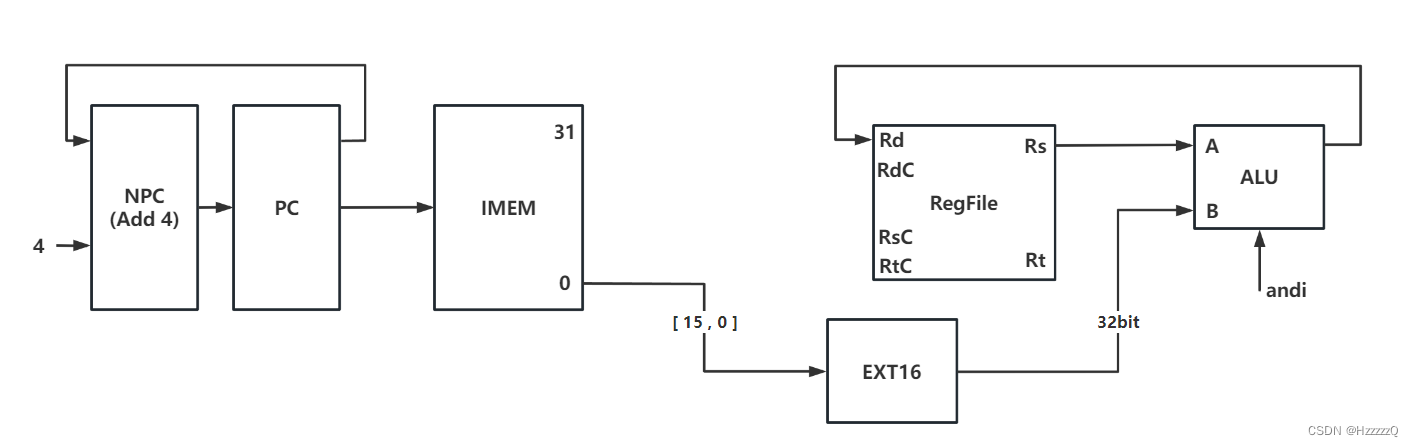
PC -> IMEM
PC + 4 -> NPC
NPC -> PC
IMEM[15:0] -> EXT16
EXT16_OUT -> B
Rs -> A
Res -> Rd
ori

PC -> IMEM
PC + 4 -> NPC
NPC -> PC
IMEM[15:0] -> EXT16
EXT16_OUT -> B
Rs -> A
Res -> Rd
xori
PC -> IMEM
PC + 4 -> NPC
NPC -> PC
IMEM[15:0] -> EXT16
EXT16_OUT -> B
Rs -> A
Res -> Rd
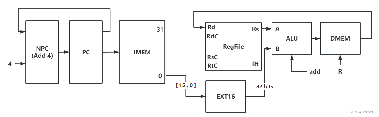
lw
Design methodology:
- Specific function of
lw
is to read the 32-bit binary number at the specified address into a
register
. This directive is mainly used to access arrays or other data structures stored in memory.- Since data needs to be loaded, a data memory
DMEM
is required.- Calculate the data of
Rs
and
EXT16_OUT
to sum it, obtain the offset data address, and read the data.- After non-jump instructions such as add being executed,
PC
(Program Counter) will point to the address of next instruction, which means a self-increment of 4. So, an independent pathway is necessary to complete this task. (Same as instructions above)Instruction
sw
is almost same with
lw
(while in
sw
RT is used as data from data storage directly given to DMEM)
PC -> IMEM
PC + 4 -> NPC
NPC -> PC
IMEM[15:0] -> EXT16
EXT16_OUT -> B
Rs -> A
Res -> DMEM_addr
DMEM_OUT -> Rd
sw
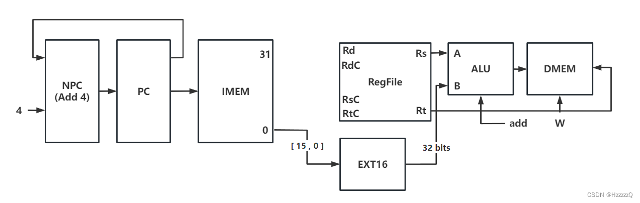
PC -> IMEM
PC + 4 -> NPC
NPC -> PC
IMEM[15:0] -> EXT16
EXT16_OUT -> B
Rs -> A
Rt -> DMEM
Res -> DMEM_addr
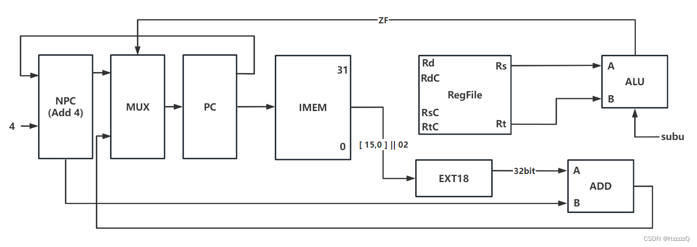
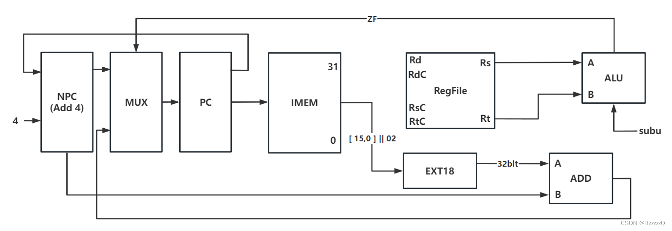
beq
Design methodology:
- The
beq
instruction compares whether the values in the two registers are
equal
, and if they are, adds an
offset
to
PC
, allowing the program to jump to another marker to continue executing the program. If they are not equal, the next instruction is executed directly sequentially.- The determination of data equality can be done using ALU’s
subu
instruction. The result will be reflected as
ZF(zero flag)
.- The choice of PC will rely on the implementation of
MUX
.Instruction
bne
is similar to
beq
.
beq
=
branch if equal
bne
=
branch if not equal
PC -> IMEM
PC + 4 -> NPC
NPC -> MUX
IMEM[15:0] || 02 -> EXT18
EXT18_OUT -> ADD
NPC -> ADD
(ZF -> MUX)
ADD_OUT -> MUX
MUX_OUT -> PC
Rs -> A
Rt -> B
bne
PC -> IMEM
PC + 4 -> NPC
NPC -> MUX
IMEM[15:0] || 02 -> EXT18
EXT18_OUT -> ADD
NPC -> ADD
(~ZF -> MUX)
ADD_OUT -> MUX
MUX_OUT -> PC
Rs -> A
Rt -> B
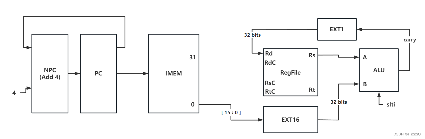
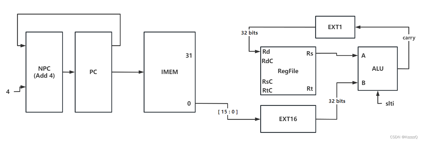
slti
Design methodology:
slti
instruction is used to load a 16-bit signed immediate number into the target register, and if the source register contains a value less than this immediate number, set the target register to 1, otherwise set to 0.- Often used in
conditional branching
and
loop control structures
to check whether a value satisfies a given condition.- Used to handle signed numbers
Instruction
sltiu
is same as
slti
.
PC -> IMEM
PC + 4 -> NPC
NPC -> PC
IMEM[15:0] -> EXT16
EXT16_OUT -> B
Rs -> A
CF -> EXT1
EXT1_OUT -> Rd
sltiu
PC -> IMEM
PC + 4 -> NPC
NPC -> PC
IMEM[15:0] -> EXT16
EXT16_OUT -> B
Rs -> A
CF -> EXT1
EXT1_OUT -> Rd
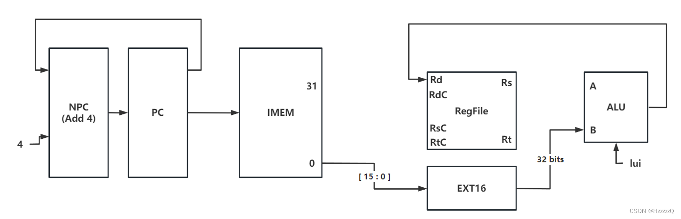
lui
Design methodology:
lui
instruction is used to shift a 16-bit immediate number left by 16 bits and store it in a register. This operation is usually used to load an unsigned 16-bit integer for a 32-bit register.- The implementation method in verilog is to
clear the lower 16 bits
.
PC -> IMEM
PC + 4 -> NPC
NPC -> PC
IMEM[15:0] -> EXT16
EXT16_OUT -> B
Res -> Rd
J-type
j
Design methodology:
j
instruction sets PC to the specified code address, so that the corresponding instruction can be executed
unconditionally
jumped to that address. (No matter what has happened, PC will jump)- There is no need for participant of
alu / regfile / dmem
…etc.
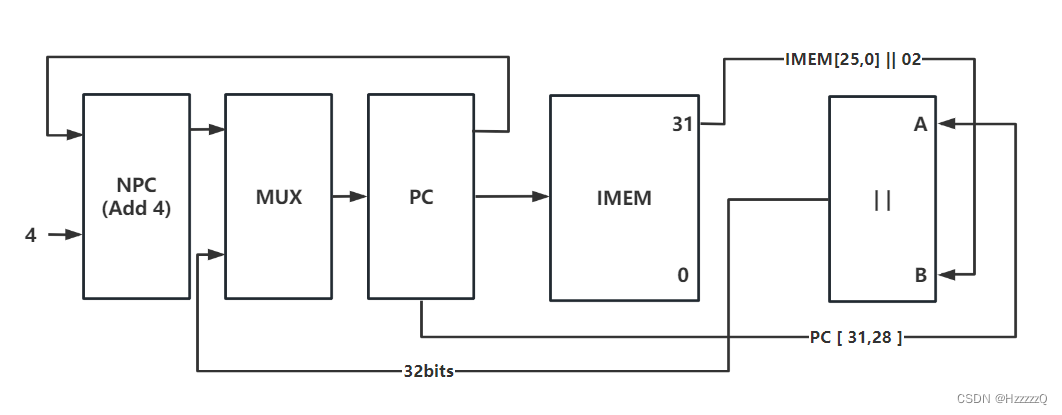
PC -> IMEM
PC[31:28] -> ||_A
IMEM[25,0] || 02 -> ||_B
||_OUT -> MUX
PC+4 -> NPC
NPC -> MUX
MUX_OUT -> PC
jal
Design methodology:
- The
jal
(Jump and Link) instruction is used to make a
jump
and
save
the return address.- When the program encounters a
jal
instruction, it saves the current PC value to register and jumps to the specified destination address to execute the code.- After the subprogram is executed, use the
jr
(Jump Register) instruction to jump back to the return address saved in register to continue executing the main program.
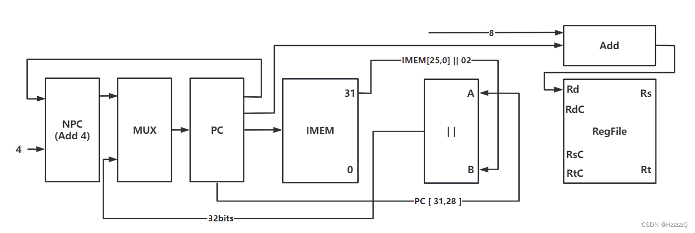
PC -> IMEM
PC[31:28] -> ||_A
IMEM[25,0] || 02 -> ||_B
||_OUT -> MUX
PC + 4 -> NPC
NPC -> MUX
MUX_OUT -> PC
PC -> ADD
8 -> ADD
ADD_OUT -> Rd
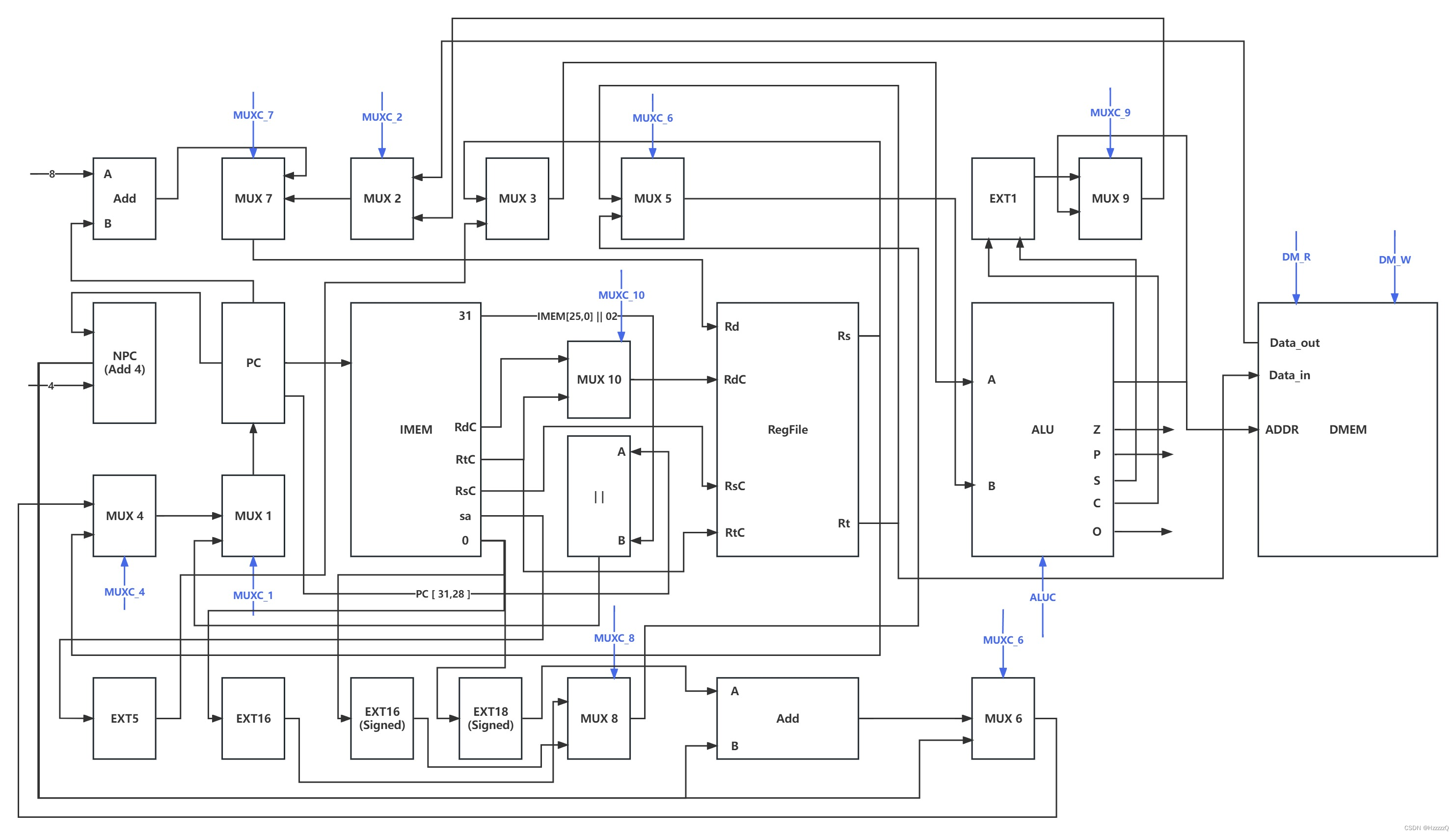
Complete Datapath