arm64汇编学习-(3)算术与移位指令
本篇博客是基于对苯叔的第三季视频的学习整理而得,大家如果想深入学习可以购买《arm64体系结构编程与实践》以及购买苯叔出品的第三季视频。
1 数据处理指令
1.1 check the C condition of adds, adc,cmp
1.1.1 测试示例程序
/*
测试adds, cmp以及adc指令的条件标志位
*/
.global add_inst_test
add_inst_test:
mov x0, #0
ldr x1, =0xffffffffffffffff
mov x2, #3
/*测试adds的进位功能,当有溢出发生时,C=1*/
adds x0, x1, x1
adc x3, xzr, xzr
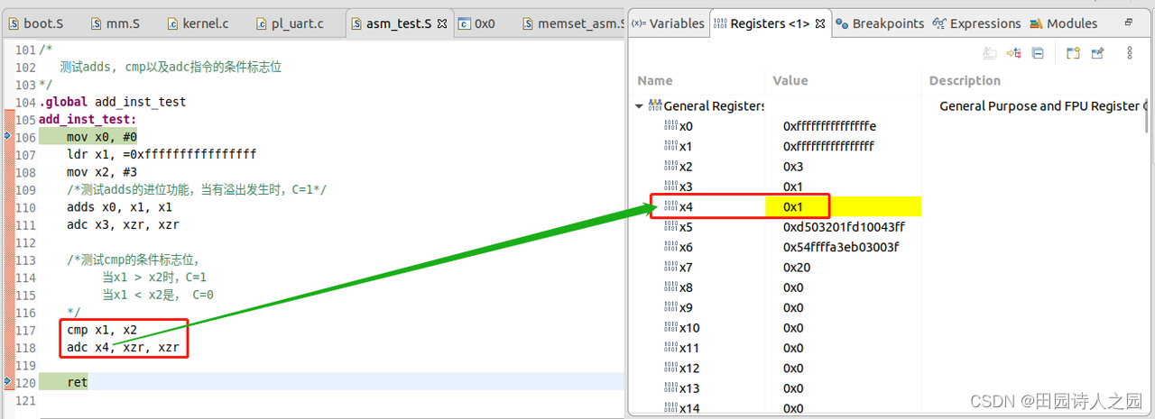
/*测试cmp的条件标志位,
当x1 > x2时,C=1
当x1 < x2是, C=0
*/
cmp x1, x2
adc x4, xzr, xzr
ret
1.1.2 执行之前
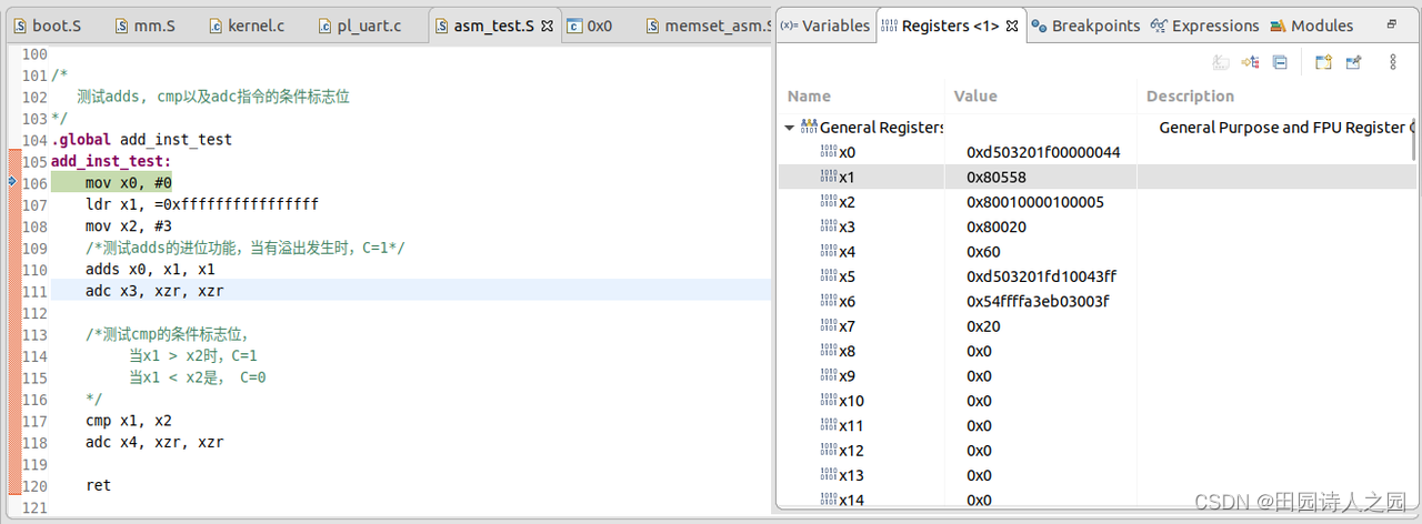
1.1.3 执行之后
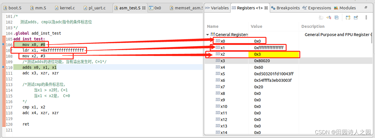
1.1.3.1 ldr和mov指令之后
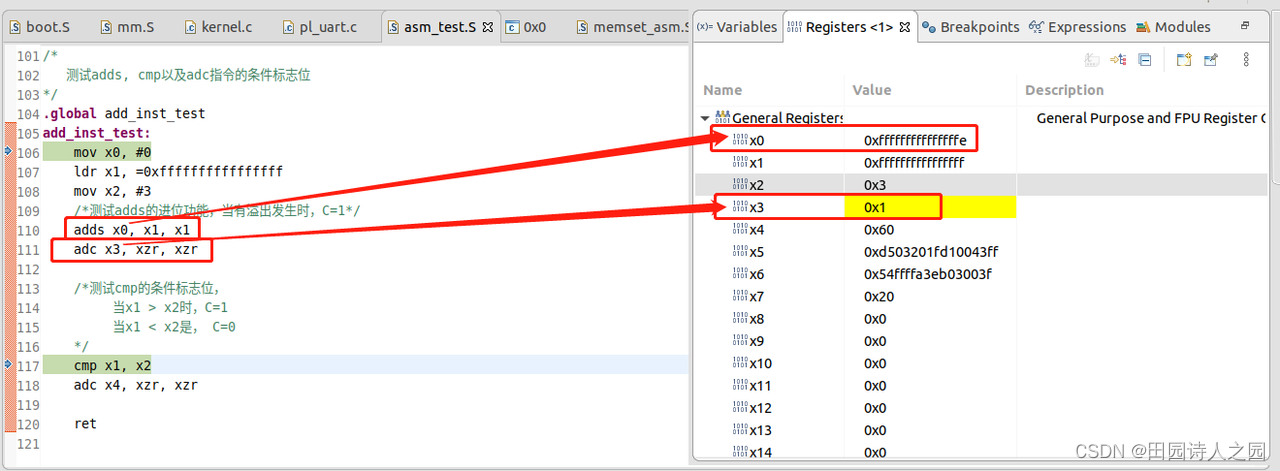
1.1.3.2 ads和adc指令之后
ADDS: Add (extended register), setting flags, adds a register value and a sign or zero-extended register value, followed by an optional left shift amount, and writes the result to the destination register. The argument that is extended from the register can be a byte, halfword, word, or doubleword. It updates the condition flags based on the result.
- ADDS , <Xn|SP>, {, {#}}
- (result, nzcv) = AddWithCarry(operand1, operand2, ‘0’);
- PSTATE.<N,Z,C,V> = nzcv;
-
X[d] = result;
ADC:Add with Carry adds two register values and the Carry flag value, and writes the result to the destination register. - (result, -) = AddWithCarry(operand1, operand2, PSTATE.C);
-
X[d] = result;
1.1.3.3 cmp和adc指令之后
CMP:This instruction is an alias of the SUBS (shifted register) instruction.
- The encodings in this description are named to match the encodings of SUBS (shifted register).
-
The description of SUBS (shifted register) gives the operational pseudocode for this instruction.
1.2 cmp和sbc指令的综合运用
1.2.1 示例代码
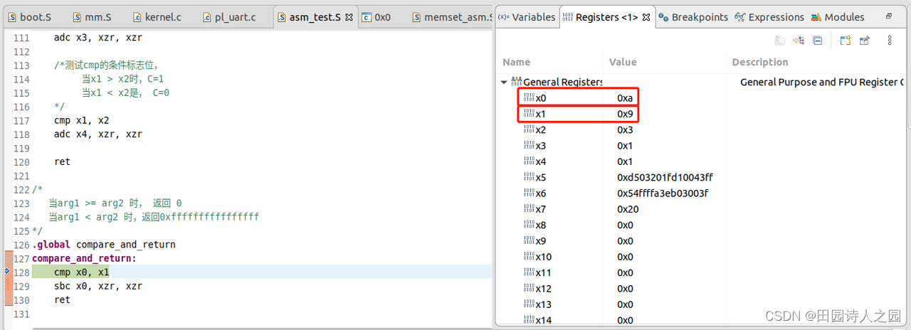
ret = compare_and_return(10, 9);
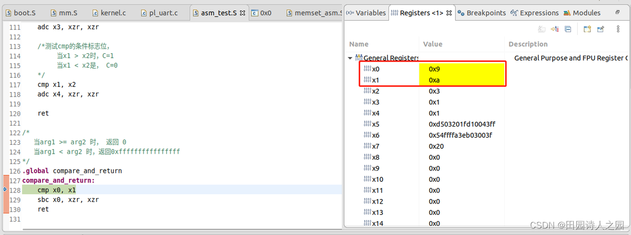
val = compare_and_return(9, 10);
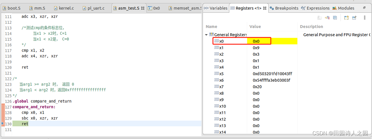
/*
当arg1 >= arg2 时, 返回 0
当arg1 < arg2 时,返回0xffffffffffffffff
*/
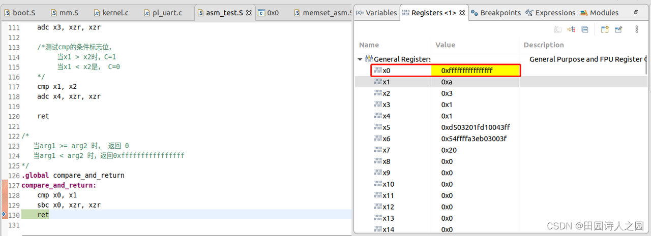
.global compare_and_return
compare_and_return:
cmp x0, x1
sbc x0, xzr, xzr
ret
1.2.2 compare_and_return(10, 9)测试之前
1.2.3 compare_and_return(10, 9)测试之后
1.2.4 compare_and_return(9, 10)测试之前
1.2.5 compare_and_return(9, 10)测试之后
1.3 测试ands指令对Z标志位的影响
2.1.3.1 示例代码
/*
data_process_instr lab3: 测试ands指令对Z标志位的影响
*/
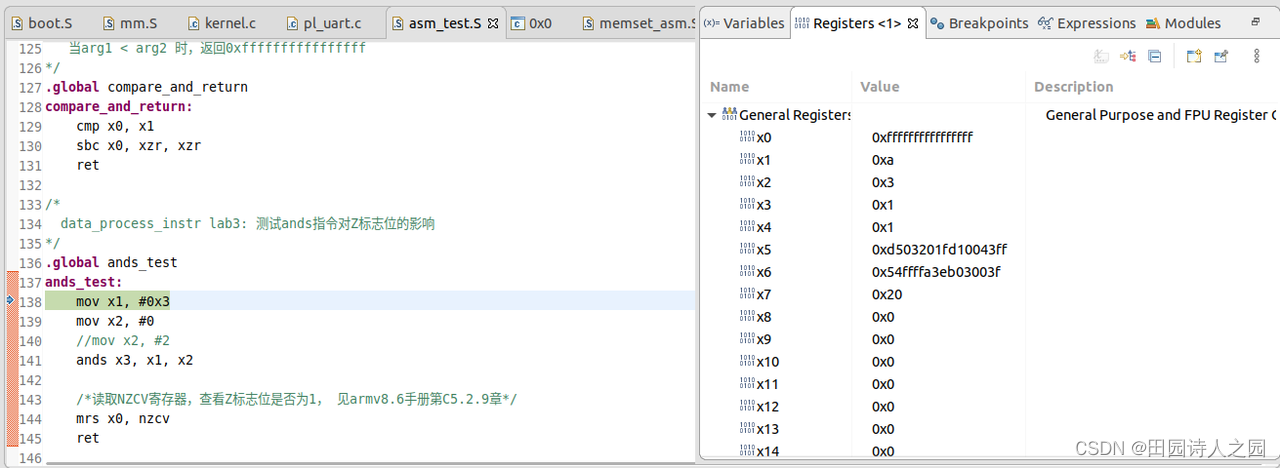
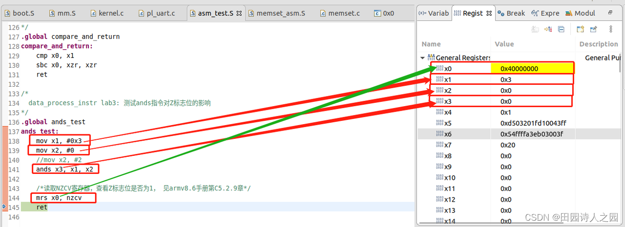
.global ands_test
ands_test:
mov x1, #0x3
mov x2, #0
//mov x2, #2
ands x3, x1, x2
/*读取NZCV寄存器,查看Z标志位是否为1, 见armv8.6手册第C5.2.9章*/
mrs x0, nzcv
ret
1.3.2 测试之前
1.3.3 测试之后
1.4 测试位段bitfield指令
1.4.1 示例代码
/*
data_process_instr lab4: 测试位段bitfield指令
*/
.global bitfield_test
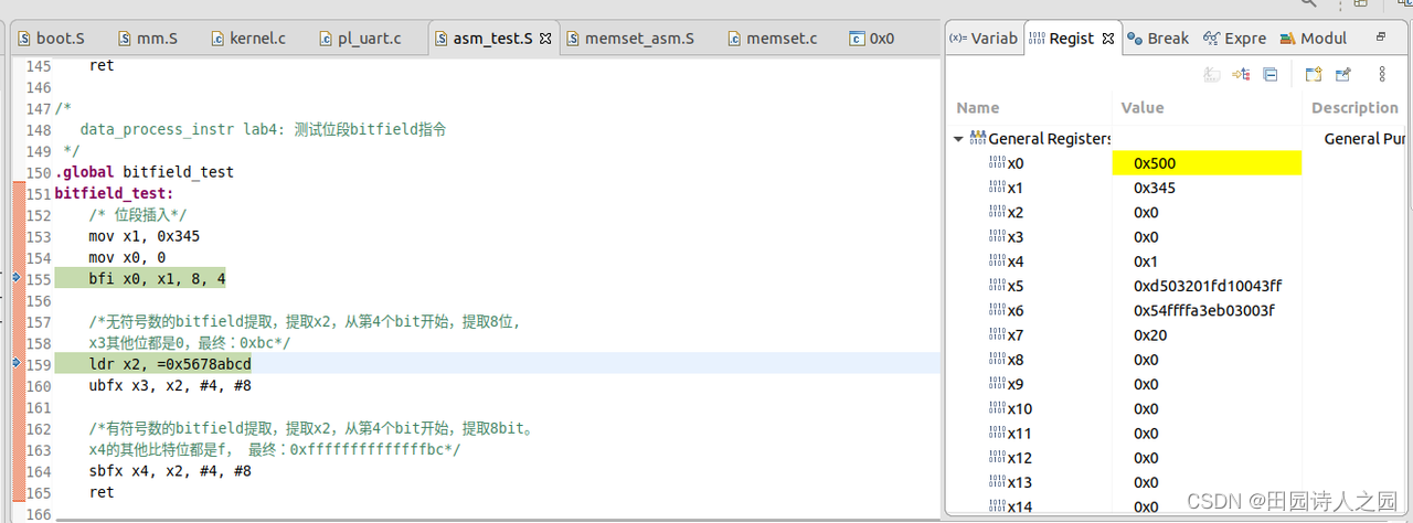
bitfield_test:
/* 位段插入*/
mov x1, 0x345
mov x0, 0
bfi x0, x1, 8, 4
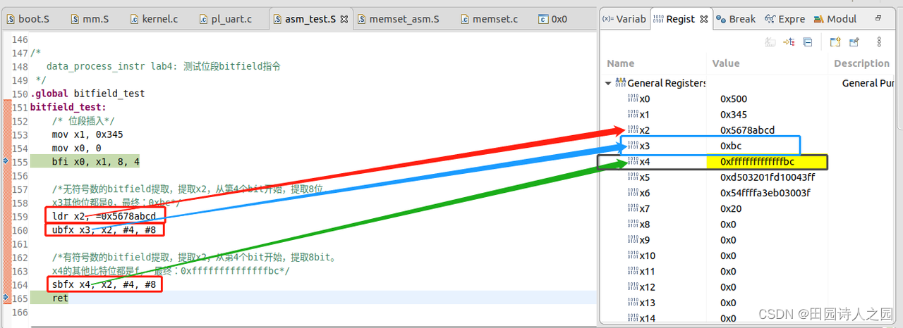
/*无符号数的bitfield提取,提取x2,从第4个bit开始,提取8位,
x3其他位都是0,最终:0xbc*/
ldr x2, =0x5678abcd
ubfx x3, x2, #4, #8
/*有符号数的bitfield提取,提取x2,从第4个bit开始,提取8bit。
x4的其他比特位都是f, 最终:0xffffffffffffffbc*/
sbfx x4, x2, #4, #8
ret
1.4.2 测试之前
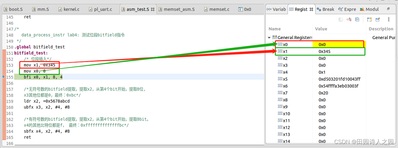
1.4.3 bfi x0, x1, 8, 4之后
BFI :Bitfield Insert copies a bitfield of bits from the least significant bits of the source register to bit position of the destination register, leaving the other destination bits unchanged.

-
bfi x0, x1, 8, 4 该汇编指令的含义为:将x1寄存器的最低4位拷贝到x0寄存器的bit 8开始的4位上去,x0寄存器的其他位不变,所以最终x0寄存器的值被设置为0x500
1.4.4 ubfx and sbfx之后
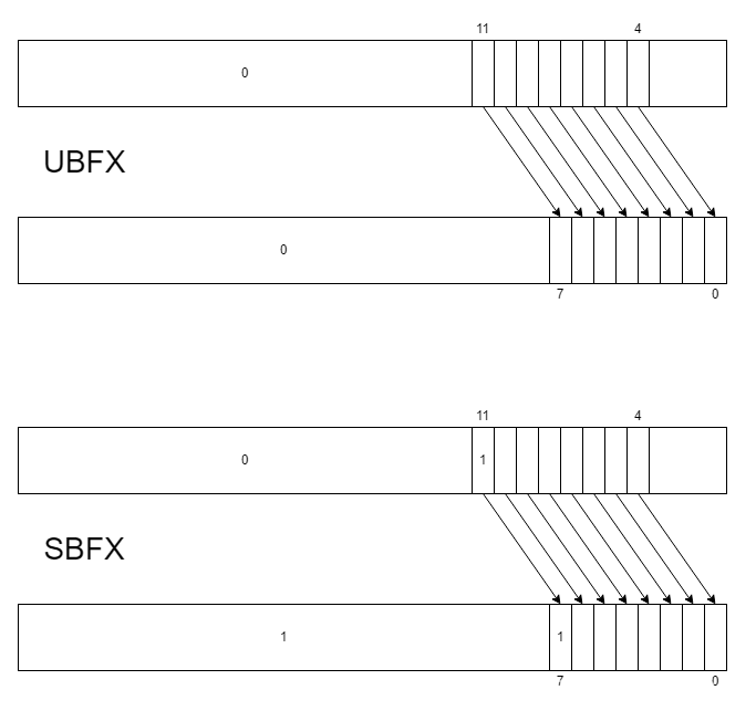
UBFX :Unsigned Bitfield Extract copies a bitfield of bits starting from bit position in the source register to the least significant bits of the destination register, and sets destination bits above the bitfield to zero.
-
UBFX , , #, #
SBFX :Signed Bitfield Extract copies a bitfield of bits starting from bit position in the source register to the least significant bits of the destination register, and sets destination bits above the bitfield to a copy of the most significant bit of the bitfield. -
SBFX , , #, #
This content is only supported in a Docs.
1.5 读取寄存器的域
1.5.1 示例代码
/*
data_process_instr lab4: 测试位段bitfield指令
*/
.global bitfield_test
bitfield_test:
/* 位段插入*/
mov x1, 0x345
mov x0, 0
bfi x0, x1, 8, 4
/*无符号数的bitfield提取,提取x2,从第4个bit开始,提取8位,
x3其他位都是0,最终:0xbc*/
ldr x2, =0x5678abcd
ubfx x3, x2, #4, #8
/*有符号数的bitfield提取,提取x2,从第4个bit开始,提取8bit。
x4的其他比特位都是f, 最终:0xffffffffffffffbc*/
sbfx x4, x2, #4, #8
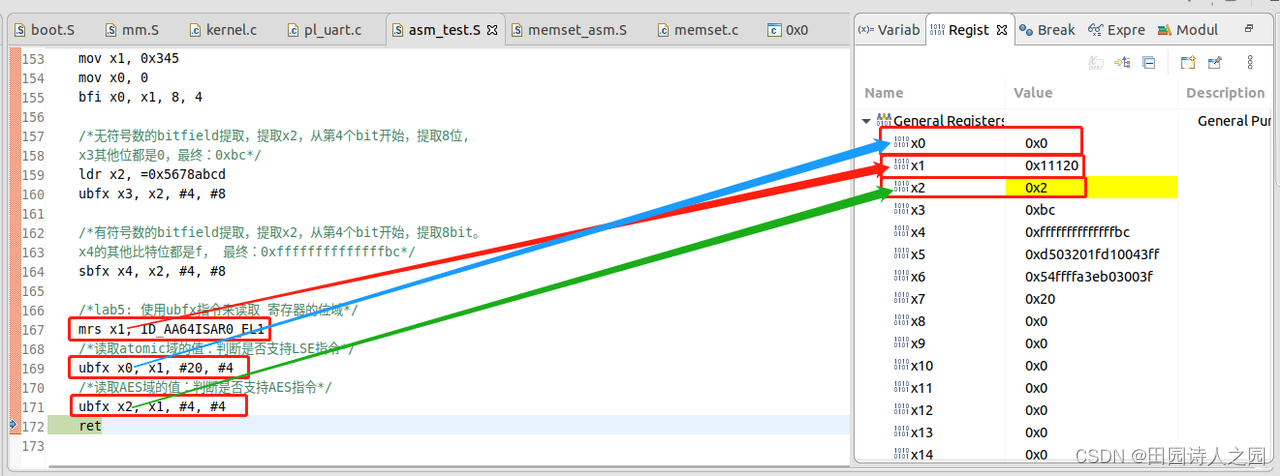
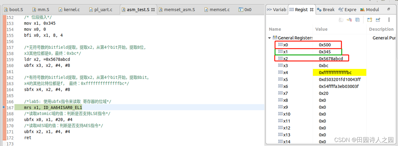
/*lab5: 使用ubfx指令来读取 寄存器的位域*/
mrs x1, ID_AA64ISAR0_EL1
/*读取atomic域的值:判断是否支持LSE指令*/
ubfx x0, x1, #20, #4
/*读取AES域的值:判断是否支持AES指令*/
ubfx x2, x1, #4, #4
ret
2.5.1.2 测试之前的状态
2.5.1.3 测试之后的状态值