1、12位ADC是一种逐次逼近型模拟数字转换器。
它有多达18个通道,可测量16个外部和2个内部信号源。
各通道的A/D转换可以单次、连续、扫描或间断模式执行。
ADC的结果可以左对齐或右对齐方式存储在16位数据寄存器中。
模拟看门狗特性允许应用程序检测输入电压是否超出用户定义的高/低阀值。
ADC 的输入时钟不得超过14MHz,它是由PCLK2经分频产生。
2、ADC主要特征
● 12位分辨率
● 转换结束、注入转换结束和发生模拟看门狗事件时产生中断
● 单次和连续转换模式
● 从通道0到通道n的自动扫描模式
● 间断模式执行
● 自校准
● 带内嵌数据一致性的数据对齐
● 采样间隔可以按通道分别编程
● 规则转换和注入转换均有外部触发选项
● 双重模式(带2个或以上ADC 的器件)
● ADC转换时间:
STM32F103xx增强型产品:时钟为56MHz时为1μs(4分频,因为最多不超过14M) (时钟为72MHz为1.17μs)(6分频)
STM32F101xx基本型产品:时钟为28MHz时为1μs (时钟为36MHz为1.55μs)
STM32F102xxUSB型产品:时钟为48MHz 时为1.2μs
STM32F105xx和STM32F107xx产品:时钟为56MHz时为1μs (时钟为72MHz为1.17μs)
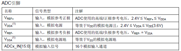
● ADC供电要求:2.4V到3.6V
● ADC输入范围:VREF- ≤ VIN ≤ VREF+
● 规则通道转换期间有DMA请求产生。
3、ADC引脚
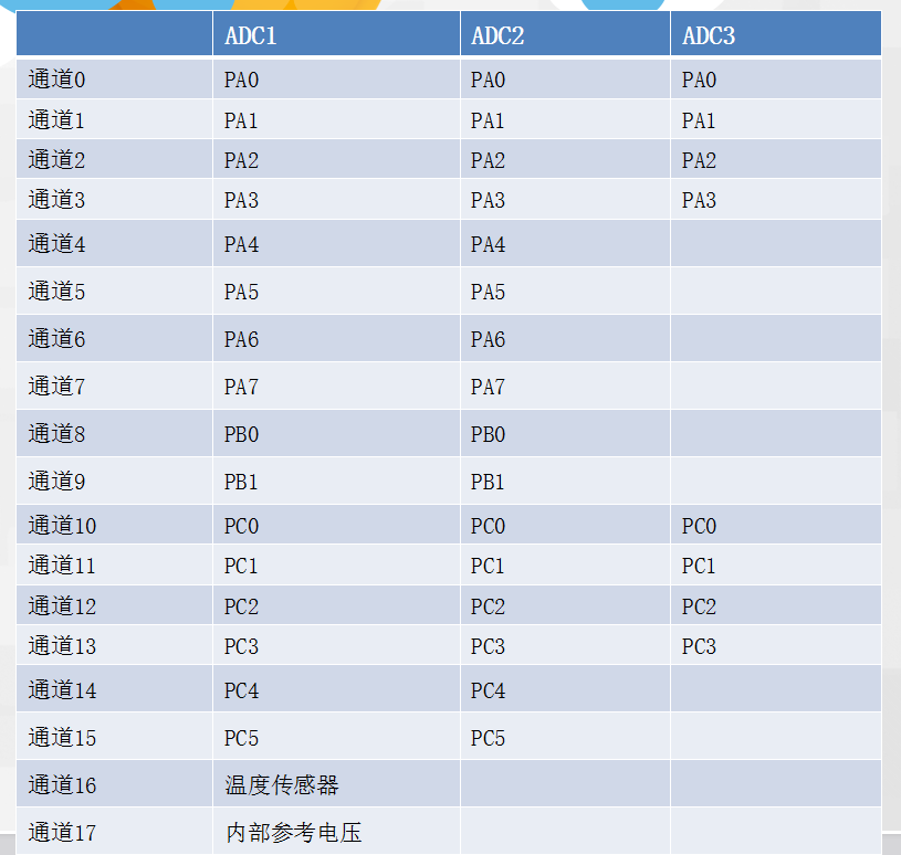
4、ADC通道
5、 有16个多路通道。可以把转换组织成两组:规则组和注入组。 在任意多个通道上以任意顺序进行的一系列转换构成成组转换。
(1)规则组由多达16个转换组成。规则通道和它们的转换顺序在ADC_SQRx寄存器中选择。
规则组中转换的总数应写入ADC_SQR1寄存器的L[3:0]位中
(2)注入组由多达4个转换组成。注入通道和它们的转换顺序在ADC_JSQR寄存器中选择。
注入组里的转换总数目应写入ADC_JSQR寄存器的L[1:0]位中。
(3)如果ADC_SQRx或ADC_JSQR寄存器在转换期间被更改,当前的转换被清除,一个新的启动脉冲将发送到ADC 以转换新选择的组。
6、温度转换器:
温度传感器和通道ADC1_IN16相连接,内部参照电压VREFINT和ADC1_IN17相连接。
可以按注入或规则通道对这两个内部通道进行转换。
注意: 温度传感器和VREFINT只能出现在主ADC1 中。
7、单词转换模式:
单次转换模式下,ADC只执行一次转换。该模式既可通过设置ADC_CR2 寄存器的ADON位(只适用于规则通道)启动也可通过外部触发启动 (适用于规则通道或注入通道),这时CONT位为0 。
一旦选择通道的转换完成:
(1)如果一个规则通道被转换:
转换数据被储存在16位ADC_DR寄存器中
EOC(转换结束)标志被设置
如果设置了EOCIE,则产生中断。
(2) 如果一个注入通道被转换:
转换数据被储存在16位的ADC_DRJ1寄存器中
JEOC(注入转换结束)标志被设置
如果设置了JEOCIE位,则产生中断。然后ADC停止。
8、连续转换模式 :
在连续转换模式中,当前面ADC转换一结束马上就启动另一次转换。 此模式可通过外部触发启动或通过设置ADC_CR2寄存器上的ADON位启动,此时CONT位是1。
每个转换后:
(1)如果一个规则通道被转换:
转换数据被储存在16位的ADC_DR寄存器中
EOC(转换结束)标志被设置
如果设置了EOCIE,则产生中断。
(2) 如果一个注入通道被转换:
转换数据被储存在16位的ADC_DRJ1寄存器中
JEOC(注入转换结束)标志被设置
如果设置了JEOCIE位,则产生中断。
9、扫描模式 :
(1) 此模式用来扫描一组模拟通道。
(2) 扫描模式可通过设置ADC_CR1寄存器的SCAN位来选择。一旦这个位被设置, ADC扫描所有被ADC_SQRX 寄存器(对规则通道)或ADC_JSQR(对注入通道)选中的所有通道。
在每个组的每个通道上执行单次转换。在每个转换结束时,同一组的下一个通道被自动转换。
如果设置了CONT位,转换不会在选择组的最后一个通道上停止,而是再次从选择组的第一个通道继续转换。
(3) 如果设置了DMA位,在每次EOC后,DMA控制器把规则组通道的转换数据传输到SRAM 中。 而注入通道转换的数据总是存储在ADC_JDRx寄存器中。
10、间断模式
(1)规则组
此模式通过设置ADC_CR1 寄存器上的DISCEN位激活。 它可以用来执行一个短序列的n次转换(n<=8),此转换是ADC_SQRx寄存器所选择的转换序列的一部分。
数值n由ADC_CR1寄存器的DISCNUM[2:0]位给出。 一个外部触发信号可以启动ADC_SQRx 寄存器中描述的下一轮n次转换,直到此序列所有的转换完成为止。
总的序列长度由ADC_SQR1寄存器的L[3:0]定义。 当以间断模式转换一个规则组时,转换序列结束后不自动从头开始。 当所有子组被转换完成,下一次触发启动第一个子组的转换。
(2)注入组
此模式通过设置ADC_CR1 寄存器的JDISCEN位激活。在一个外部触发事件后,该模式按通道顺序逐个转换ADC_JSQR寄存器中选择的序列。
一个外部触发信号可以启动ADC_JSQR寄存器选择的下一个通道序列的转换,直到序列中所有的转换完成为止。总的序列长度由ADC_JSQR寄存器的JL[1:0]位定义。
当完成所有注入通道转换,下个触发启动第1个注入通道的转换。不能同时使用自动注入和间断模式。 必须避免同时为规则和注入组设置间断模式。间断模式只能作用 于一组转换。
11、ADC时钟配置
(1)输入参数范围:
#define RCC_PCLK2_Div2 ((uint32_t)0x00000000)
#define RCC_PCLK2_Div4 ((uint32_t)0x00004000)
#define RCC_PCLK2_Div6 ((uint32_t)0x00008000)
#define RCC_PCLK2_Div8 ((uint32_t)0x0000C000)
(2)STM32的ADC最大的转换速率为1Mhz,也就是转换时间为1us(在ADCCLK=14M,采样周期为1.5个ADC时钟下得到), 不要让ADC的时钟超过14M,否则将导致结果准确度下降。
12、ADC的采样时间
(1)ADC 使用若干个ADC_CLK 周期对输入电压采样,采样周期数目可以通过ADC_SMPR1 和ADC_SMPR2寄存器中的SMP[2:0]位更改。 每个通道可以分别用不同的时间采样。
(2)总转换时间如下计算:
TCONV = 采样时间+ 12.5个周期
例如:当ADCCLK=14MHz ,采样时间为1.5周期 TCONV = 1.5 + 12.5 = 14周期 = 1μs
(3)常见的周期有:
1.5周期、7.5周期、13.5周期、28.5周期、41.5周期、55.5周期、71.5周期、239.5周期。
13、数据对齐
(1) ADC_CR2寄存器中的ALIGN位选择转换后数据储存的对齐方式。数据可以左对齐或右对齐,
(2)注入组通道转换的数据值已经减去了在ADC_JOFRx寄存器中定义的偏移量,因此结果可以是一个负值。SEXT位是扩展的符号值。
(3)对于规则组通道,不需减去偏移值,因此只有12个位有效。

14、校准
(1) ADC有一个内置自校准模式。校准可大幅减小因内部电容器组的变化而造成的准精度误差。在校准期间,在每个电容器上都会计算出一个误差修正码(数字值),
这个码用于消除在随后的转换 中每个电容器上产生的误差。
(2) 通过设置ADC_CR2寄存器的CAL位启动校准。一旦校准结束,CAL位被硬件复位,可以开始正常转换。建议在上电时执行一次ADC校准。
校准阶段结束后,校准码储存在ADC_DR 中。
(3)建议在每次上电后执行一次校准,启动校准前,ADC必须处于关电状态(ADON=’0’)超过至少两个ADC时钟周期。
15、程序例程:


  1 /*************************************************************************************************************************************
  2 *
  3 *  文件名称:main.c
  4 *  文件功能:主函数文件
  5 *
  6 ***************************************************************************************************************************************/
  7
  8 #include "pbdata.h"//调用自定义公共函数库
  9
 10
 11 /*********************************************************************************
 12 *
 13 * 初始化操作
 14 *
 15 *********************************************************************************/
 16 void RCC_Configuration(void);//系统时钟初始化函数声明
 17 void GPIO_Configuration(void);//GPIO初始化函数声明
 18 void NVIC_Configuration(void);//中断优先级配置函数声明
 19 void USART_Configuration(void);//串口配置函数声明
 20 void ADC_Configuration(void);//ADC配置函数声明
 21
 22
 23
 24 /********************************************************************************
 25 *
 26 *  函数名称:main(void)
 27 *  函数功能:主函数
 28 *  函数说明:不能用void定义主函数
 29 *
 30 ********************************************************************************/
 31 int main(void)//void不能void定义主函数
 32 {
 33
 34     u32 ad=0;//取50次转换平均值
 35     u8  i=0;//循环50次
 36
 37     RCC_Configuration();    //系统时钟初始化
 38
 39     GPIO_Configuration();//端口初始化
 40
 41     USART_Configuration();//串口配置
 42
 43     NVIC_Configuration();
 44
 45     ADC_Configuration();//ADC配置
 46
 47
 48     while(1)
 49     {
 50         ad=0;
 51         for(i=0;i<50;i++)
 52         {
 53             ADC_SoftwareStartConvCmd(ADC1,ENABLE);//启动AD转换
 54             while(!ADC_GetFlagStatus(ADC1, ADC_FLAG_EOC));//等待转换完成
 55             ad+= ADC_GetConversionValue(ADC1);
 56         }
 57
 58         ad=ad/50;
 59         printf("AD=%.3f\n",ad*3.3/4095);
 60
 61         delay_ms(3000);
 62
 63     }
 64
 65 }
 66
 67
 68
 69
 70 /********************************************************************************
 71 *
 72 *  函数名称:RCC_Configuration(void)
 73 *  函数功能:系统时钟高初始化函数
 74 *
 75 ********************************************************************************/
 76     void RCC_Configuration(void)//系统时钟高初始化函数
 77   {
 78
 79     SystemInit();//系统初始化
 80     RCC_APB2PeriphClockCmd(RCC_APB2Periph_GPIOA,ENABLE);//串口对应GPIO时钟使能
 81         RCC_APB2PeriphClockCmd(RCC_APB2Periph_USART1,ENABLE);//串口时钟使能
 82         RCC_APB2PeriphClockCmd(RCC_APB2Periph_AFIO,ENABLE);//引脚复用
 83
 84         RCC_APB2PeriphClockCmd(RCC_APB2Periph_GPIOC,ENABLE);//adc对应GPIO时钟使能
 85         RCC_APB2PeriphClockCmd(RCC_APB2Periph_ADC1,ENABLE);//ADC1时钟使能
 86         RCC_ADCCLKConfig(RCC_PCLK2_Div6);//ADC频率不超过14M,所以对它分频,72/6=12
 87
 88     }
 89
 90
 91
 92 /*******************************************************************************
 93 *
 94 * 函数名称:GPIO_Configuration(void)
 95 * 函数功能:GPIO初始化函数
 96 *
 97 ********************************************************************************/
 98
 99     void GPIO_Configuration(void)//GPIO初始化函数
100   {
101
102
103 /*串口引脚配置*/
104         GPIO_InitTypeDef GPIO_InitStructure;//定义一个GPIO设置的结构体变量
105
106 /*输出引脚配置*/
107         /*结构体变量赋值*/
108       GPIO_InitStructure.GPIO_Pin=GPIO_Pin_9;////引脚配置TX
109       GPIO_InitStructure.GPIO_Speed=GPIO_Speed_50MHz;//配置频率
110         GPIO_InitStructure.GPIO_Mode=GPIO_Mode_AF_PP;//发送要配置成复用推挽输出
111         /*对应的GPIO初始化*/
112       GPIO_Init(GPIOA,&GPIO_InitStructure);
113
114
115 /*输入引脚配置*/
116         /*结构体变量赋值*/
117       GPIO_InitStructure.GPIO_Pin=GPIO_Pin_10;////引脚配置RX
118         GPIO_InitStructure.GPIO_Mode=GPIO_Mode_IN_FLOATING;//接收引脚配置成浮空输入
119         /*对应的GPIO初始化*/
120       GPIO_Init(GPIOA,&GPIO_InitStructure);
121
122 /*ADC输入引脚配置*/
123         /*结构体变量赋值*/
124       GPIO_InitStructure.GPIO_Pin=GPIO_Pin_0;////引脚配置adc
125         GPIO_InitStructure.GPIO_Mode=GPIO_Mode_AIN;//模拟输入
126         /*对应的GPIO初始化*/
127       GPIO_Init(GPIOC,&GPIO_InitStructure);
128
129
130
131
132   }
133
134
135 /********************************************************************************
136 *
137 *  函数名称:NVIC_Configuration(void)
138 *  函数功能:配置中断优先级
139 *
140 ********************************************************************************/
141
142 void NVIC_Configuration(void)
143 {
144   NVIC_InitTypeDef NVIC_InitStructure; //定义一个优先级配置结构体变量
145
146   NVIC_PriorityGroupConfig(NVIC_PriorityGroup_1);//分组
147
148   NVIC_InitStructure.NVIC_IRQChannel = USART1_IRQn;
149   NVIC_InitStructure.NVIC_IRQChannelPreemptionPriority = 0;//抢断优先级
150   NVIC_InitStructure.NVIC_IRQChannelSubPriority = 1;//响应优先级
151   NVIC_InitStructure.NVIC_IRQChannelCmd = ENABLE;//使能
152
153   NVIC_Init(&NVIC_InitStructure);//初始化
154 }
155
156
157 /*********************************************************************************
158 *
159 *  函数名称:USART_Configuration(void)
160 *  函数功能:串口配置函数
161 *
162 *********************************************************************************/
163 void USART_Configuration(void)
164 {
165 /*定义串口配置结构体变量*/
166         USART_InitTypeDef USART_InitStructure;//定义一个串口配置结构体变量
167
168
169 /*结构体变量赋值*/
170     USART_InitStructure.USART_BaudRate = 9600;//波特率9600
171     USART_InitStructure.USART_WordLength = USART_WordLength_8b;//位宽,8位
172     USART_InitStructure.USART_StopBits = USART_StopBits_1;//停止位1
173     USART_InitStructure.USART_Parity = USART_Parity_No;//不奇偶校验
174     USART_InitStructure.USART_HardwareFlowControl = USART_HardwareFlowControl_None;//流控禁止
175     USART_InitStructure.USART_Mode = USART_Mode_Tx | USART_Mode_Rx;//发送使能
176
177
178 /*发送串口配置初始化*/
179     USART_Init(USART1, &USART_InitStructure);
180
181
182 /*打开串口接收中断*/
183       USART_ITConfig(USART1,USART_IT_RXNE,ENABLE);//当接收到数据时,会产生中断
184
185
186 /*打开串口*/
187     USART_Cmd(USART1,ENABLE);//串口使能,打开
188
189 /*清空中断标志位*/
190     USART_ClearFlag(USART1,USART_FLAG_TC);
191 }
192
193
194
195 /*********************************************************************************
196 *
197 *  函数名称:ADC_Configuration(void)
198 *  函数功能:串口配置函数
199 *
200 *********************************************************************************/
201 void ADC_Configuration(void)
202 {
203
204 /*定义一个ADC配置结构体变量*/
205     ADC_InitTypeDef ADC_InitStructure;
206
207
208 /*对结构体变量赋值*/
209   ADC_InitStructure.ADC_Mode = ADC_Mode_Independent;//独立模式
210   ADC_InitStructure.ADC_ScanConvMode = DISABLE;//单通道模式
211   ADC_InitStructure.ADC_ContinuousConvMode = DISABLE;//单次采集
212   ADC_InitStructure.ADC_ExternalTrigConv = ADC_ExternalTrigConv_None;//软件触发
213   ADC_InitStructure.ADC_DataAlign = ADC_DataAlign_Right;//右对其
214   ADC_InitStructure.ADC_NbrOfChannel = 1;//转换的通道,只取1个通道
215
216 /*ADC初始化*/
217   ADC_Init(ADC1, &ADC_InitStructure);
218
219
220 /*规则组*/
221   ADC_RegularChannelConfig(ADC1, ADC_Channel_10, 1,ADC_SampleTime_239Cycles5);    //,选择ADC1,通道10,通道数1,采样时间239.5
222
223
224 /*使能ADC*/
225    ADC_Cmd(ADC1, ENABLE);
226
227
228 /*校准ADC*/
229    ADC_ResetCalibration(ADC1);//对应ADC复位
230      while(ADC_GetResetCalibrationStatus(ADC1));//获取状态,等待复位完成
231      ADC_StartCalibration(ADC1);//开始指定ADC校准状态
232      while(ADC_GetCalibrationStatus(ADC1));//获取校准状态,等待完成
233
234
235 /*启动ADC*/
236      ADC_SoftwareStartConvCmd(ADC1,ENABLE);
237
238
239 }
240
241
242
243
244
245
246
247
248
249
250
251
252
253
254
255
256
257
258
259
260
261
262
263
264
265
266
267
268
269
270
View Code
  1 /****************************************************************************************************************
  2 *
  3 * 文件名称:pbdata.c
  4 * 文件功能:自定义函数或者全局变量的初始化
  5 *
  6 ****************************************************************************************************************/
  7
  8 /*头文件声明*/
  9 #include "pbdata.h"
 10
 11
 12
 13
 14 /********************************************************************************************
 15 *
 16 * 自定义全局变量
 17 *
 18 ********************************************************************************************/
 19 u8 dt=0;
 20
 21
 22
 23
 24
 25 /******************************************************************************************
 26 *
 27 * 自定义函数
 28 *
 29 ******************************************************************************************/
 30
 31
 32
 33 /**************************************************
 34 *
 35 *  函数名称:delay_us(u32 nus)
 36 *  函数功能:微秒延时函数
 37 *  输入参数:输入值为延时us
 38 *
 39 ***************************************************/
 40 void delay_us(u32 nus)
 41 {
 42     u32 temp;
 43     SysTick->LOAD = 9*nus;//载入初值,72M/8=9M,也就是1/9us,9*1/9us,所以是执行9次
 44     SysTick->VAL=0X00;//清空计数器,清空后,就自动设置自己设定的计数器的值
 45     SysTick->CTRL=0X01;//使能,减到零动作(不发生中断),采用外部时钟
 46
 47     do
 48     {
 49           temp=SysTick->CTRL;//标志位,等到一直减到0
 50          }while((temp&0x01)&&(!(temp&(1<<16))));//等待时间到达
 51
 52     SysTick->CTRL=0x00; //关闭计数器
 53     SysTick->VAL =0X00; //清空计数器
 54 }
 55
 56
 57
 58
 59
 60
 61
 62 /***************************************************
 63 *
 64 * 函数名称:delay_ms(u16 nms)
 65 * 函数功能:毫秒级延时
 66 * 输入参数:输入值位延时ms
 67 *
 68 ****************************************************/
 69 void delay_ms(u16 nms)
 70 {
 71     u32 temp;
 72     SysTick->LOAD = 9000*nms;//载入初值,72M/8=9M,也就是1/9us,9*1/9us,所以是执行9000次
 73     SysTick->VAL=0X00;//清空计数器,清空后,就自动设置自己设定的计数器的值
 74     SysTick->CTRL=0X01;//使能,减到零动作(不发生中断),采用外部时钟
 75
 76     do
 77     {
 78           temp=SysTick->CTRL;//标志位,等到一直减到0
 79          }while((temp&0x01)&&(!(temp&(1<<16))));//等待时间到达
 80
 81     SysTick->CTRL=0x00; //关闭计数器
 82     SysTick->VAL =0X00; //清空计数器
 83 }
 84
 85
 86
 87 /****************************************************
 88 *
 89 * 重定义printf函数部分
 90 *
 91 ****************************************************/
 92 int fputc(int ch,FILE *F)
 93 {
 94
 95     USART_SendData(USART1,(u8)ch);
 96
 97     while(USART_GetFlagStatus(USART1,USART_FLAG_TXE)==RESET);//等待发送完成,判断标志位
 98
 99     return ch;
100 }
View Code
 1 /*pbdata.h*/
 2 /***************************************************************************************************
 3 *
 4 * 文件名称:pbdata.h
 5 * 文件功能:自定义的函数和全局变量的声明头文件
 6 *
 7 ***************************************************************************************************/
 8
 9 #ifndef _pbdata_H
10 #define _pbdata_H
11
12
13
14
15
16 /********************************************************************
17 *
18 *  调用的头文件放在这里
19 *
20 ********************************************************************/
21 #include "stm32f10x.h"
22 #include "misc.h"
23 #include "stm32f10x_exti.h"
24 #include "stm32f10x_tim.h"
25 #include "stm32f10x_usart.h"
26 #include "stm32f10x_adc.h"
27 #include "stdio.h"
28
29
30
31
32 /********************************************************************
33 *
34 *  自定义全局变量声明
35 *
36 ********************************************************************/
37 extern u8 dt;
38
39
40
41
42
43 /********************************************************************
44 *
45 *  自定义全函数声明
46 *
47 ********************************************************************/
48 void delay(u32 nCount);
49 void delay_us(u32 nus);
50 void delay_ms(u16 nms);
51 int fputc(int ch,FILE *F);
52
53
54
55 #endif
View Code
1 /** 2 ****************************************************************************** 3 * @file stm32f10x_adc.c 4 * @author MCD Application Team 5 * @version V3.5.0 6 * @date 11-March-2011 7 * @brief This file provides all the ADC firmware functions. 8 ****************************************************************************** 9 * @attention 10 * 11 * THE PRESENT FIRMWARE WHICH IS FOR GUIDANCE ONLY AIMS AT PROVIDING CUSTOMERS 12 * WITH CODING INFORMATION REGARDING THEIR PRODUCTS IN ORDER FOR THEM TO SAVE 13 * TIME. AS A RESULT, STMICROELECTRONICS SHALL NOT BE HELD LIABLE FOR ANY 14 * DIRECT, INDIRECT OR CONSEQUENTIAL DAMAGES WITH RESPECT TO ANY CLAIMS ARISING 15 * FROM THE CONTENT OF SUCH FIRMWARE AND/OR THE USE MADE BY CUSTOMERS OF THE 16 * CODING INFORMATION CONTAINED HEREIN IN CONNECTION WITH THEIR PRODUCTS. 17 * 18 * <h2><center>© COPYRIGHT 2011 STMicroelectronics</center></h2> 19 ****************************************************************************** 20 */ 21 22 /* Includes ------------------------------------------------------------------*/ 23 #include "stm32f10x_adc.h" 24 #include "stm32f10x_rcc.h" 25 26 /** @addtogroup STM32F10x_StdPeriph_Driver 27 * @{ 28 */ 29 30 /** @defgroup ADC 31 * @brief ADC driver modules 32 * @{ 33 */ 34 35 /** @defgroup ADC_Private_TypesDefinitions 36 * @{ 37 */ 38 39 /** 40 * @} 41 */ 42 43 /** @defgroup ADC_Private_Defines 44 * @{ 45 */ 46 47 /* ADC DISCNUM mask */ 48 #define CR1_DISCNUM_Reset ((uint32_t)0xFFFF1FFF) 49 50 /* ADC DISCEN mask */ 51 #define CR1_DISCEN_Set ((uint32_t)0x00000800) 52 #define CR1_DISCEN_Reset ((uint32_t)0xFFFFF7FF) 53 54 /* ADC JAUTO mask */ 55 #define CR1_JAUTO_Set ((uint32_t)0x00000400) 56 #define CR1_JAUTO_Reset ((uint32_t)0xFFFFFBFF) 57 58 /* ADC JDISCEN mask */ 59 #define CR1_JDISCEN_Set ((uint32_t)0x00001000) 60 #define CR1_JDISCEN_Reset ((uint32_t)0xFFFFEFFF) 61 62 /* ADC AWDCH mask */ 63 #define CR1_AWDCH_Reset ((uint32_t)0xFFFFFFE0) 64 65 /* ADC Analog watchdog enable mode mask */ 66 #define CR1_AWDMode_Reset ((uint32_t)0xFF3FFDFF) 67 68 /* CR1 register Mask */ 69 #define CR1_CLEAR_Mask ((uint32_t)0xFFF0FEFF) 70 71 /* ADC ADON mask */ 72 #define CR2_ADON_Set ((uint32_t)0x00000001) 73 #define CR2_ADON_Reset ((uint32_t)0xFFFFFFFE) 74 75 /* ADC DMA mask */ 76 #define CR2_DMA_Set ((uint32_t)0x00000100) 77 #define CR2_DMA_Reset ((uint32_t)0xFFFFFEFF) 78 79 /* ADC RSTCAL mask */ 80 #define CR2_RSTCAL_Set ((uint32_t)0x00000008) 81 82 /* ADC CAL mask */ 83 #define CR2_CAL_Set ((uint32_t)0x00000004) 84 85 /* ADC SWSTART mask */ 86 #define CR2_SWSTART_Set ((uint32_t)0x00400000) 87 88 /* ADC EXTTRIG mask */ 89 #define CR2_EXTTRIG_Set ((uint32_t)0x00100000) 90 #define CR2_EXTTRIG_Reset ((uint32_t)0xFFEFFFFF) 91 92 /* ADC Software start mask */ 93 #define CR2_EXTTRIG_SWSTART_Set ((uint32_t)0x00500000) 94 #define CR2_EXTTRIG_SWSTART_Reset ((uint32_t)0xFFAFFFFF) 95 96 /* ADC JEXTSEL mask */ 97 #define CR2_JEXTSEL_Reset ((uint32_t)0xFFFF8FFF) 98 99 /* ADC JEXTTRIG mask */ 100 #define CR2_JEXTTRIG_Set ((uint32_t)0x00008000) 101 #define CR2_JEXTTRIG_Reset ((uint32_t)0xFFFF7FFF) 102 103 /* ADC JSWSTART mask */ 104 #define CR2_JSWSTART_Set ((uint32_t)0x00200000) 105 106 /* ADC injected software start mask */ 107 #define CR2_JEXTTRIG_JSWSTART_Set ((uint32_t)0x00208000) 108 #define CR2_JEXTTRIG_JSWSTART_Reset ((uint32_t)0xFFDF7FFF) 109 110 /* ADC TSPD mask */ 111 #define CR2_TSVREFE_Set ((uint32_t)0x00800000) 112 #define CR2_TSVREFE_Reset ((uint32_t)0xFF7FFFFF) 113 114 /* CR2 register Mask */ 115 #define CR2_CLEAR_Mask ((uint32_t)0xFFF1F7FD) 116 117 /* ADC SQx mask */ 118 #define SQR3_SQ_Set ((uint32_t)0x0000001F) 119 #define SQR2_SQ_Set ((uint32_t)0x0000001F) 120 #define SQR1_SQ_Set ((uint32_t)0x0000001F) 121 122 /* SQR1 register Mask */ 123 #define SQR1_CLEAR_Mask ((uint32_t)0xFF0FFFFF) 124 125 /* ADC JSQx mask */ 126 #define JSQR_JSQ_Set ((uint32_t)0x0000001F) 127 128 /* ADC JL mask */ 129 #define JSQR_JL_Set ((uint32_t)0x00300000) 130 #define JSQR_JL_Reset ((uint32_t)0xFFCFFFFF) 131 132 /* ADC SMPx mask */ 133 #define SMPR1_SMP_Set ((uint32_t)0x00000007) 134 #define SMPR2_SMP_Set ((uint32_t)0x00000007) 135 136 /* ADC JDRx registers offset */ 137 #define JDR_Offset ((uint8_t)0x28) 138 139 /* ADC1 DR register base address */ 140 #define DR_ADDRESS ((uint32_t)0x4001244C) 141 142 /** 143 * @} 144 */ 145 146 /** @defgroup ADC_Private_Macros 147 * @{ 148 */ 149 150 /** 151 * @} 152 */ 153 154 /** @defgroup ADC_Private_Variables 155 * @{ 156 */ 157 158 /** 159 * @} 160 */ 161 162 /** @defgroup ADC_Private_FunctionPrototypes 163 * @{ 164 */ 165 166 /** 167 * @} 168 */ 169 170 /** @defgroup ADC_Private_Functions 171 * @{ 172 */ 173 174 /** 175 * @brief Deinitializes the ADCx peripheral registers to their default reset values. 176 * @param ADCx: where x can be 1, 2 or 3 to select the ADC peripheral. 177 * @retval None 178 */ 179 void ADC_DeInit(ADC_TypeDef* ADCx) 180 { 181 /* Check the parameters */ 182 assert_param(IS_ADC_ALL_PERIPH(ADCx)); 183 184 if (ADCx == ADC1) 185 { 186 /* Enable ADC1 reset state */ 187 RCC_APB2PeriphResetCmd(RCC_APB2Periph_ADC1, ENABLE); 188 /* Release ADC1 from reset state */ 189 RCC_APB2PeriphResetCmd(RCC_APB2Periph_ADC1, DISABLE); 190 } 191 else if (ADCx == ADC2) 192 { 193 /* Enable ADC2 reset state */ 194 RCC_APB2PeriphResetCmd(RCC_APB2Periph_ADC2, ENABLE); 195 /* Release ADC2 from reset state */ 196 RCC_APB2PeriphResetCmd(RCC_APB2Periph_ADC2, DISABLE); 197 } 198 else 199 { 200 if (ADCx == ADC3) 201 { 202 /* Enable ADC3 reset state */ 203 RCC_APB2PeriphResetCmd(RCC_APB2Periph_ADC3, ENABLE); 204 /* Release ADC3 from reset state */ 205 RCC_APB2PeriphResetCmd(RCC_APB2Periph_ADC3, DISABLE); 206 } 207 } 208 } 209 210 /** 211 * @brief Initializes the ADCx peripheral according to the specified parameters 212 * in the ADC_InitStruct. 213 * @param ADCx: where x can be 1, 2 or 3 to select the ADC peripheral. 214 * @param ADC_InitStruct: pointer to an ADC_InitTypeDef structure that contains 215 * the configuration information for the specified ADC peripheral. 216 * @retval None 217 */ 218 void ADC_Init(ADC_TypeDef* ADCx, ADC_InitTypeDef* ADC_InitStruct) 219 { 220 uint32_t tmpreg1 = 0; 221 uint8_t tmpreg2 = 0; 222 /* Check the parameters */ 223 assert_param(IS_ADC_ALL_PERIPH(ADCx)); 224 assert_param(IS_ADC_MODE(ADC_InitStruct->ADC_Mode)); 225 assert_param(IS_FUNCTIONAL_STATE(ADC_InitStruct->ADC_ScanConvMode)); 226 assert_param(IS_FUNCTIONAL_STATE(ADC_InitStruct->ADC_ContinuousConvMode)); 227 assert_param(IS_ADC_EXT_TRIG(ADC_InitStruct->ADC_ExternalTrigConv)); 228 assert_param(IS_ADC_DATA_ALIGN(ADC_InitStruct->ADC_DataAlign)); 229 assert_param(IS_ADC_REGULAR_LENGTH(ADC_InitStruct->ADC_NbrOfChannel)); 230 231 /*---------------------------- ADCx CR1 Configuration -----------------*/ 232 /* Get the ADCx CR1 value */ 233 tmpreg1 = ADCx->CR1; 234 /* Clear DUALMOD and SCAN bits */ 235 tmpreg1 &= CR1_CLEAR_Mask; 236 /* Configure ADCx: Dual mode and scan conversion mode */ 237 /* Set DUALMOD bits according to ADC_Mode value */ 238 /* Set SCAN bit according to ADC_ScanConvMode value */ 239 tmpreg1 |= (uint32_t)(ADC_InitStruct->ADC_Mode | ((uint32_t)ADC_InitStruct->ADC_ScanConvMode << 8)); 240 /* Write to ADCx CR1 */ 241 ADCx->CR1 = tmpreg1; 242 243 /*---------------------------- ADCx CR2 Configuration -----------------*/ 244 /* Get the ADCx CR2 value */ 245 tmpreg1 = ADCx->CR2; 246 /* Clear CONT, ALIGN and EXTSEL bits */ 247 tmpreg1 &= CR2_CLEAR_Mask; 248 /* Configure ADCx: external trigger event and continuous conversion mode */ 249 /* Set ALIGN bit according to ADC_DataAlign value */ 250 /* Set EXTSEL bits according to ADC_ExternalTrigConv value */ 251 /* Set CONT bit according to ADC_ContinuousConvMode value */ 252 tmpreg1 |= (uint32_t)(ADC_InitStruct->ADC_DataAlign | ADC_InitStruct->ADC_ExternalTrigConv | 253 ((uint32_t)ADC_InitStruct->ADC_ContinuousConvMode << 1)); 254 /* Write to ADCx CR2 */ 255 ADCx->CR2 = tmpreg1; 256 257 /*---------------------------- ADCx SQR1 Configuration -----------------*/ 258 /* Get the ADCx SQR1 value */ 259 tmpreg1 = ADCx->SQR1; 260 /* Clear L bits */ 261 tmpreg1 &= SQR1_CLEAR_Mask; 262 /* Configure ADCx: regular channel sequence length */ 263 /* Set L bits according to ADC_NbrOfChannel value */ 264 tmpreg2 |= (uint8_t) (ADC_InitStruct->ADC_NbrOfChannel - (uint8_t)1); 265 tmpreg1 |= (uint32_t)tmpreg2 << 20; 266 /* Write to ADCx SQR1 */ 267 ADCx->SQR1 = tmpreg1; 268 } 269 270 /** 271 * @brief Fills each ADC_InitStruct member with its default value. 272 * @param ADC_InitStruct : pointer to an ADC_InitTypeDef structure which will be initialized. 273 * @retval None 274 */ 275 void ADC_StructInit(ADC_InitTypeDef* ADC_InitStruct) 276 { 277 /* Reset ADC init structure parameters values */ 278 /* Initialize the ADC_Mode member */ 279 ADC_InitStruct->ADC_Mode = ADC_Mode_Independent; 280 /* initialize the ADC_ScanConvMode member */ 281 ADC_InitStruct->ADC_ScanConvMode = DISABLE; 282 /* Initialize the ADC_ContinuousConvMode member */ 283 ADC_InitStruct->ADC_ContinuousConvMode = DISABLE; 284 /* Initialize the ADC_ExternalTrigConv member */ 285 ADC_InitStruct->ADC_ExternalTrigConv = ADC_ExternalTrigConv_T1_CC1; 286 /* Initialize the ADC_DataAlign member */ 287 ADC_InitStruct->ADC_DataAlign = ADC_DataAlign_Right; 288 /* Initialize the ADC_NbrOfChannel member */ 289 ADC_InitStruct->ADC_NbrOfChannel = 1; 290 } 291 292 /** 293 * @brief Enables or disables the specified ADC peripheral. 294 * @param ADCx: where x can be 1, 2 or 3 to select the ADC peripheral. 295 * @param NewState: new state of the ADCx peripheral. 296 * This parameter can be: ENABLE or DISABLE. 297 * @retval None 298 */ 299 void ADC_Cmd(ADC_TypeDef* ADCx, FunctionalState NewState) 300 { 301 /* Check the parameters */ 302 assert_param(IS_ADC_ALL_PERIPH(ADCx)); 303 assert_param(IS_FUNCTIONAL_STATE(NewState)); 304 if (NewState != DISABLE) 305 { 306 /* Set the ADON bit to wake up the ADC from power down mode */ 307 ADCx->CR2 |= CR2_ADON_Set; 308 } 309 else 310 { 311 /* Disable the selected ADC peripheral */ 312 ADCx->CR2 &= CR2_ADON_Reset; 313 } 314 } 315 316 /** 317 * @brief Enables or disables the specified ADC DMA request. 318 * @param ADCx: where x can be 1 or 3 to select the ADC peripheral. 319 * Note: ADC2 hasn't a DMA capability. 320 * @param NewState: new state of the selected ADC DMA transfer. 321 * This parameter can be: ENABLE or DISABLE. 322 * @retval None 323 */ 324 void ADC_DMACmd(ADC_TypeDef* ADCx, FunctionalState NewState) 325 { 326 /* Check the parameters */ 327 assert_param(IS_ADC_DMA_PERIPH(ADCx)); 328 assert_param(IS_FUNCTIONAL_STATE(NewState)); 329 if (NewState != DISABLE) 330 { 331 /* Enable the selected ADC DMA request */ 332 ADCx->CR2 |= CR2_DMA_Set; 333 } 334 else 335 { 336 /* Disable the selected ADC DMA request */ 337 ADCx->CR2 &= CR2_DMA_Reset; 338 } 339 } 340 341 /** 342 * @brief Enables or disables the specified ADC interrupts. 343 * @param ADCx: where x can be 1, 2 or 3 to select the ADC peripheral. 344 * @param ADC_IT: specifies the ADC interrupt sources to be enabled or disabled. 345 * This parameter can be any combination of the following values: 346 * @arg ADC_IT_EOC: End of conversion interrupt mask 347 * @arg ADC_IT_AWD: Analog watchdog interrupt mask 348 * @arg ADC_IT_JEOC: End of injected conversion interrupt mask 349 * @param NewState: new state of the specified ADC interrupts. 350 * This parameter can be: ENABLE or DISABLE. 351 * @retval None 352 */ 353 void ADC_ITConfig(ADC_TypeDef* ADCx, uint16_t ADC_IT, FunctionalState NewState) 354 { 355 uint8_t itmask = 0; 356 /* Check the parameters */ 357 assert_param(IS_ADC_ALL_PERIPH(ADCx)); 358 assert_param(IS_FUNCTIONAL_STATE(NewState)); 359 assert_param(IS_ADC_IT(ADC_IT)); 360 /* Get the ADC IT index */ 361 itmask = (uint8_t)ADC_IT; 362 if (NewState != DISABLE) 363 { 364 /* Enable the selected ADC interrupts */ 365 ADCx->CR1 |= itmask; 366 } 367 else 368 { 369 /* Disable the selected ADC interrupts */ 370 ADCx->CR1 &= (~(uint32_t)itmask); 371 } 372 } 373 374 /** 375 * @brief Resets the selected ADC calibration registers. 376 * @param ADCx: where x can be 1, 2 or 3 to select the ADC peripheral. 377 * @retval None 378 */ 379 void ADC_ResetCalibration(ADC_TypeDef* ADCx) 380 { 381 /* Check the parameters */ 382 assert_param(IS_ADC_ALL_PERIPH(ADCx)); 383 /* Resets the selected ADC calibration registers */ 384 ADCx->CR2 |= CR2_RSTCAL_Set; 385 } 386 387 /** 388 * @brief Gets the selected ADC reset calibration registers status. 389 * @param ADCx: where x can be 1, 2 or 3 to select the ADC peripheral. 390 * @retval The new state of ADC reset calibration registers (SET or RESET). 391 */ 392 FlagStatus ADC_GetResetCalibrationStatus(ADC_TypeDef* ADCx) 393 { 394 FlagStatus bitstatus = RESET; 395 /* Check the parameters */ 396 assert_param(IS_ADC_ALL_PERIPH(ADCx)); 397 /* Check the status of RSTCAL bit */ 398 if ((ADCx->CR2 & CR2_RSTCAL_Set) != (uint32_t)RESET) 399 { 400 /* RSTCAL bit is set */ 401 bitstatus = SET; 402 } 403 else 404 { 405 /* RSTCAL bit is reset */ 406 bitstatus = RESET; 407 } 408 /* Return the RSTCAL bit status */ 409 return bitstatus; 410 } 411 412 /** 413 * @brief Starts the selected ADC calibration process. 414 * @param ADCx: where x can be 1, 2 or 3 to select the ADC peripheral. 415 * @retval None 416 */ 417 void ADC_StartCalibration(ADC_TypeDef* ADCx) 418 { 419 /* Check the parameters */ 420 assert_param(IS_ADC_ALL_PERIPH(ADCx)); 421 /* Enable the selected ADC calibration process */ 422 ADCx->CR2 |= CR2_CAL_Set; 423 } 424 425 /** 426 * @brief Gets the selected ADC calibration status. 427 * @param ADCx: where x can be 1, 2 or 3 to select the ADC peripheral. 428 * @retval The new state of ADC calibration (SET or RESET). 429 */ 430 FlagStatus ADC_GetCalibrationStatus(ADC_TypeDef* ADCx) 431 { 432 FlagStatus bitstatus = RESET; 433 /* Check the parameters */ 434 assert_param(IS_ADC_ALL_PERIPH(ADCx)); 435 /* Check the status of CAL bit */ 436 if ((ADCx->CR2 & CR2_CAL_Set) != (uint32_t)RESET) 437 { 438 /* CAL bit is set: calibration on going */ 439 bitstatus = SET; 440 } 441 else 442 { 443 /* CAL bit is reset: end of calibration */ 444 bitstatus = RESET; 445 } 446 /* Return the CAL bit status */ 447 return bitstatus; 448 } 449 450 /** 451 * @brief Enables or disables the selected ADC software start conversion . 452 * @param ADCx: where x can be 1, 2 or 3 to select the ADC peripheral. 453 * @param NewState: new state of the selected ADC software start conversion. 454 * This parameter can be: ENABLE or DISABLE. 455 * @retval None 456 */ 457 void ADC_SoftwareStartConvCmd(ADC_TypeDef* ADCx, FunctionalState NewState) 458 { 459 /* Check the parameters */ 460 assert_param(IS_ADC_ALL_PERIPH(ADCx)); 461 assert_param(IS_FUNCTIONAL_STATE(NewState)); 462 if (NewState != DISABLE) 463 { 464 /* Enable the selected ADC conversion on external event and start the selected 465 ADC conversion */ 466 ADCx->CR2 |= CR2_EXTTRIG_SWSTART_Set; 467 } 468 else 469 { 470 /* Disable the selected ADC conversion on external event and stop the selected 471 ADC conversion */ 472 ADCx->CR2 &= CR2_EXTTRIG_SWSTART_Reset; 473 } 474 } 475 476 /** 477 * @brief Gets the selected ADC Software start conversion Status. 478 * @param ADCx: where x can be 1, 2 or 3 to select the ADC peripheral. 479 * @retval The new state of ADC software start conversion (SET or RESET). 480 */ 481 FlagStatus ADC_GetSoftwareStartConvStatus(ADC_TypeDef* ADCx) 482 { 483 FlagStatus bitstatus = RESET; 484 /* Check the parameters */ 485 assert_param(IS_ADC_ALL_PERIPH(ADCx)); 486 /* Check the status of SWSTART bit */ 487 if ((ADCx->CR2 & CR2_SWSTART_Set) != (uint32_t)RESET) 488 { 489 /* SWSTART bit is set */ 490 bitstatus = SET; 491 } 492 else 493 { 494 /* SWSTART bit is reset */ 495 bitstatus = RESET; 496 } 497 /* Return the SWSTART bit status */ 498 return bitstatus; 499 } 500 501 /** 502 * @brief Configures the discontinuous mode for the selected ADC regular 503 * group channel. 504 * @param ADCx: where x can be 1, 2 or 3 to select the ADC peripheral. 505 * @param Number: specifies the discontinuous mode regular channel 506 * count value. This number must be between 1 and 8. 507 * @retval None 508 */ 509 void ADC_DiscModeChannelCountConfig(ADC_TypeDef* ADCx, uint8_t Number) 510 { 511 uint32_t tmpreg1 = 0; 512 uint32_t tmpreg2 = 0; 513 /* Check the parameters */ 514 assert_param(IS_ADC_ALL_PERIPH(ADCx)); 515 assert_param(IS_ADC_REGULAR_DISC_NUMBER(Number)); 516 /* Get the old register value */ 517 tmpreg1 = ADCx->CR1; 518 /* Clear the old discontinuous mode channel count */ 519 tmpreg1 &= CR1_DISCNUM_Reset; 520 /* Set the discontinuous mode channel count */ 521 tmpreg2 = Number - 1; 522 tmpreg1 |= tmpreg2 << 13; 523 /* Store the new register value */ 524 ADCx->CR1 = tmpreg1; 525 } 526 527 /** 528 * @brief Enables or disables the discontinuous mode on regular group 529 * channel for the specified ADC 530 * @param ADCx: where x can be 1, 2 or 3 to select the ADC peripheral. 531 * @param NewState: new state of the selected ADC discontinuous mode 532 * on regular group channel. 533 * This parameter can be: ENABLE or DISABLE. 534 * @retval None 535 */ 536 void ADC_DiscModeCmd(ADC_TypeDef* ADCx, FunctionalState NewState) 537 { 538 /* Check the parameters */ 539 assert_param(IS_ADC_ALL_PERIPH(ADCx)); 540 assert_param(IS_FUNCTIONAL_STATE(NewState)); 541 if (NewState != DISABLE) 542 { 543 /* Enable the selected ADC regular discontinuous mode */ 544 ADCx->CR1 |= CR1_DISCEN_Set; 545 } 546 else 547 { 548 /* Disable the selected ADC regular discontinuous mode */ 549 ADCx->CR1 &= CR1_DISCEN_Reset; 550 } 551 } 552 553 /** 554 * @brief Configures for the selected ADC regular channel its corresponding 555 * rank in the sequencer and its sample time. 556 * @param ADCx: where x can be 1, 2 or 3 to select the ADC peripheral. 557 * @param ADC_Channel: the ADC channel to configure. 558 * This parameter can be one of the following values: 559 * @arg ADC_Channel_0: ADC Channel0 selected 560 * @arg ADC_Channel_1: ADC Channel1 selected 561 * @arg ADC_Channel_2: ADC Channel2 selected 562 * @arg ADC_Channel_3: ADC Channel3 selected 563 * @arg ADC_Channel_4: ADC Channel4 selected 564 * @arg ADC_Channel_5: ADC Channel5 selected 565 * @arg ADC_Channel_6: ADC Channel6 selected 566 * @arg ADC_Channel_7: ADC Channel7 selected 567 * @arg ADC_Channel_8: ADC Channel8 selected 568 * @arg ADC_Channel_9: ADC Channel9 selected 569 * @arg ADC_Channel_10: ADC Channel10 selected 570 * @arg ADC_Channel_11: ADC Channel11 selected 571 * @arg ADC_Channel_12: ADC Channel12 selected 572 * @arg ADC_Channel_13: ADC Channel13 selected 573 * @arg ADC_Channel_14: ADC Channel14 selected 574 * @arg ADC_Channel_15: ADC Channel15 selected 575 * @arg ADC_Channel_16: ADC Channel16 selected 576 * @arg ADC_Channel_17: ADC Channel17 selected 577 * @param Rank: The rank in the regular group sequencer. This parameter must be between 1 to 16. 578 * @param ADC_SampleTime: The sample time value to be set for the selected channel. 579 * This parameter can be one of the following values: 580 * @arg ADC_SampleTime_1Cycles5: Sample time equal to 1.5 cycles 581 * @arg ADC_SampleTime_7Cycles5: Sample time equal to 7.5 cycles 582 * @arg ADC_SampleTime_13Cycles5: Sample time equal to 13.5 cycles 583 * @arg ADC_SampleTime_28Cycles5: Sample time equal to 28.5 cycles 584 * @arg ADC_SampleTime_41Cycles5: Sample time equal to 41.5 cycles 585 * @arg ADC_SampleTime_55Cycles5: Sample time equal to 55.5 cycles 586 * @arg ADC_SampleTime_71Cycles5: Sample time equal to 71.5 cycles 587 * @arg ADC_SampleTime_239Cycles5: Sample time equal to 239.5 cycles 588 * @retval None 589 */ 590 void ADC_RegularChannelConfig(ADC_TypeDef* ADCx, uint8_t ADC_Channel, uint8_t Rank, uint8_t ADC_SampleTime) 591 { 592 uint32_t tmpreg1 = 0, tmpreg2 = 0; 593 /* Check the parameters */ 594 assert_param(IS_ADC_ALL_PERIPH(ADCx)); 595 assert_param(IS_ADC_CHANNEL(ADC_Channel)); 596 assert_param(IS_ADC_REGULAR_RANK(Rank)); 597 assert_param(IS_ADC_SAMPLE_TIME(ADC_SampleTime)); 598 /* if ADC_Channel_10 ... ADC_Channel_17 is selected */ 599 if (ADC_Channel > ADC_Channel_9) 600 { 601 /* Get the old register value */ 602 tmpreg1 = ADCx->SMPR1; 603 /* Calculate the mask to clear */ 604 tmpreg2 = SMPR1_SMP_Set << (3 * (ADC_Channel - 10)); 605 /* Clear the old channel sample time */ 606 tmpreg1 &= ~tmpreg2; 607 /* Calculate the mask to set */ 608 tmpreg2 = (uint32_t)ADC_SampleTime << (3 * (ADC_Channel - 10)); 609 /* Set the new channel sample time */ 610 tmpreg1 |= tmpreg2; 611 /* Store the new register value */ 612 ADCx->SMPR1 = tmpreg1; 613 } 614 else /* ADC_Channel include in ADC_Channel_[0..9] */ 615 { 616 /* Get the old register value */ 617 tmpreg1 = ADCx->SMPR2; 618 /* Calculate the mask to clear */ 619 tmpreg2 = SMPR2_SMP_Set << (3 * ADC_Channel); 620 /* Clear the old channel sample time */ 621 tmpreg1 &= ~tmpreg2; 622 /* Calculate the mask to set */ 623 tmpreg2 = (uint32_t)ADC_SampleTime << (3 * ADC_Channel); 624 /* Set the new channel sample time */ 625 tmpreg1 |= tmpreg2; 626 /* Store the new register value */ 627 ADCx->SMPR2 = tmpreg1; 628 } 629 /* For Rank 1 to 6 */ 630 if (Rank < 7) 631 { 632 /* Get the old register value */ 633 tmpreg1 = ADCx->SQR3; 634 /* Calculate the mask to clear */ 635 tmpreg2 = SQR3_SQ_Set << (5 * (Rank - 1)); 636 /* Clear the old SQx bits for the selected rank */ 637 tmpreg1 &= ~tmpreg2; 638 /* Calculate the mask to set */ 639 tmpreg2 = (uint32_t)ADC_Channel << (5 * (Rank - 1)); 640 /* Set the SQx bits for the selected rank */ 641 tmpreg1 |= tmpreg2; 642 /* Store the new register value */ 643 ADCx->SQR3 = tmpreg1; 644 } 645 /* For Rank 7 to 12 */ 646 else if (Rank < 13) 647 { 648 /* Get the old register value */ 649 tmpreg1 = ADCx->SQR2; 650 /* Calculate the mask to clear */ 651 tmpreg2 = SQR2_SQ_Set << (5 * (Rank - 7)); 652 /* Clear the old SQx bits for the selected rank */ 653 tmpreg1 &= ~tmpreg2; 654 /* Calculate the mask to set */ 655 tmpreg2 = (uint32_t)ADC_Channel << (5 * (Rank - 7)); 656 /* Set the SQx bits for the selected rank */ 657 tmpreg1 |= tmpreg2; 658 /* Store the new register value */ 659 ADCx->SQR2 = tmpreg1; 660 } 661 /* For Rank 13 to 16 */ 662 else 663 { 664 /* Get the old register value */ 665 tmpreg1 = ADCx->SQR1; 666 /* Calculate the mask to clear */ 667 tmpreg2 = SQR1_SQ_Set << (5 * (Rank - 13)); 668 /* Clear the old SQx bits for the selected rank */ 669 tmpreg1 &= ~tmpreg2; 670 /* Calculate the mask to set */ 671 tmpreg2 = (uint32_t)ADC_Channel << (5 * (Rank - 13)); 672 /* Set the SQx bits for the selected rank */ 673 tmpreg1 |= tmpreg2; 674 /* Store the new register value */ 675 ADCx->SQR1 = tmpreg1; 676 } 677 } 678 679 /** 680 * @brief Enables or disables the ADCx conversion through external trigger. 681 * @param ADCx: where x can be 1, 2 or 3 to select the ADC peripheral. 682 * @param NewState: new state of the selected ADC external trigger start of conversion. 683 * This parameter can be: ENABLE or DISABLE. 684 * @retval None 685 */ 686 void ADC_ExternalTrigConvCmd(ADC_TypeDef* ADCx, FunctionalState NewState) 687 { 688 /* Check the parameters */ 689 assert_param(IS_ADC_ALL_PERIPH(ADCx)); 690 assert_param(IS_FUNCTIONAL_STATE(NewState)); 691 if (NewState != DISABLE) 692 { 693 /* Enable the selected ADC conversion on external event */ 694 ADCx->CR2 |= CR2_EXTTRIG_Set; 695 } 696 else 697 { 698 /* Disable the selected ADC conversion on external event */ 699 ADCx->CR2 &= CR2_EXTTRIG_Reset; 700 } 701 } 702 703 /** 704 * @brief Returns the last ADCx conversion result data for regular channel. 705 * @param ADCx: where x can be 1, 2 or 3 to select the ADC peripheral. 706 * @retval The Data conversion value. 707 */ 708 uint16_t ADC_GetConversionValue(ADC_TypeDef* ADCx) 709 { 710 /* Check the parameters */ 711 assert_param(IS_ADC_ALL_PERIPH(ADCx)); 712 /* Return the selected ADC conversion value */ 713 return (uint16_t) ADCx->DR; 714 } 715 716 /** 717 * @brief Returns the last ADC1 and ADC2 conversion result data in dual mode. 718 * @retval The Data conversion value. 719 */ 720 uint32_t ADC_GetDualModeConversionValue(void) 721 { 722 /* Return the dual mode conversion value */ 723 return (*(__IO uint32_t *) DR_ADDRESS); 724 } 725 726 /** 727 * @brief Enables or disables the selected ADC automatic injected group 728 * conversion after regular one. 729 * @param ADCx: where x can be 1, 2 or 3 to select the ADC peripheral. 730 * @param NewState: new state of the selected ADC auto injected conversion 731 * This parameter can be: ENABLE or DISABLE. 732 * @retval None 733 */ 734 void ADC_AutoInjectedConvCmd(ADC_TypeDef* ADCx, FunctionalState NewState) 735 { 736 /* Check the parameters */ 737 assert_param(IS_ADC_ALL_PERIPH(ADCx)); 738 assert_param(IS_FUNCTIONAL_STATE(NewState)); 739 if (NewState != DISABLE) 740 { 741 /* Enable the selected ADC automatic injected group conversion */ 742 ADCx->CR1 |= CR1_JAUTO_Set; 743 } 744 else 745 { 746 /* Disable the selected ADC automatic injected group conversion */ 747 ADCx->CR1 &= CR1_JAUTO_Reset; 748 } 749 } 750 751 /** 752 * @brief Enables or disables the discontinuous mode for injected group 753 * channel for the specified ADC 754 * @param ADCx: where x can be 1, 2 or 3 to select the ADC peripheral. 755 * @param NewState: new state of the selected ADC discontinuous mode 756 * on injected group channel. 757 * This parameter can be: ENABLE or DISABLE. 758 * @retval None 759 */ 760 void ADC_InjectedDiscModeCmd(ADC_TypeDef* ADCx, FunctionalState NewState) 761 { 762 /* Check the parameters */ 763 assert_param(IS_ADC_ALL_PERIPH(ADCx)); 764 assert_param(IS_FUNCTIONAL_STATE(NewState)); 765 if (NewState != DISABLE) 766 { 767 /* Enable the selected ADC injected discontinuous mode */ 768 ADCx->CR1 |= CR1_JDISCEN_Set; 769 } 770 else 771 { 772 /* Disable the selected ADC injected discontinuous mode */ 773 ADCx->CR1 &= CR1_JDISCEN_Reset; 774 } 775 } 776 777 /** 778 * @brief Configures the ADCx external trigger for injected channels conversion. 779 * @param ADCx: where x can be 1, 2 or 3 to select the ADC peripheral. 780 * @param ADC_ExternalTrigInjecConv: specifies the ADC trigger to start injected conversion. 781 * This parameter can be one of the following values: 782 * @arg ADC_ExternalTrigInjecConv_T1_TRGO: Timer1 TRGO event selected (for ADC1, ADC2 and ADC3) 783 * @arg ADC_ExternalTrigInjecConv_T1_CC4: Timer1 capture compare4 selected (for ADC1, ADC2 and ADC3) 784 * @arg ADC_ExternalTrigInjecConv_T2_TRGO: Timer2 TRGO event selected (for ADC1 and ADC2) 785 * @arg ADC_ExternalTrigInjecConv_T2_CC1: Timer2 capture compare1 selected (for ADC1 and ADC2) 786 * @arg ADC_ExternalTrigInjecConv_T3_CC4: Timer3 capture compare4 selected (for ADC1 and ADC2) 787 * @arg ADC_ExternalTrigInjecConv_T4_TRGO: Timer4 TRGO event selected (for ADC1 and ADC2) 788 * @arg ADC_ExternalTrigInjecConv_Ext_IT15_TIM8_CC4: External interrupt line 15 or Timer8 789 * capture compare4 event selected (for ADC1 and ADC2) 790 * @arg ADC_ExternalTrigInjecConv_T4_CC3: Timer4 capture compare3 selected (for ADC3 only) 791 * @arg ADC_ExternalTrigInjecConv_T8_CC2: Timer8 capture compare2 selected (for ADC3 only) 792 * @arg ADC_ExternalTrigInjecConv_T8_CC4: Timer8 capture compare4 selected (for ADC3 only) 793 * @arg ADC_ExternalTrigInjecConv_T5_TRGO: Timer5 TRGO event selected (for ADC3 only) 794 * @arg ADC_ExternalTrigInjecConv_T5_CC4: Timer5 capture compare4 selected (for ADC3 only) 795 * @arg ADC_ExternalTrigInjecConv_None: Injected conversion started by software and not 796 * by external trigger (for ADC1, ADC2 and ADC3) 797 * @retval None 798 */ 799 void ADC_ExternalTrigInjectedConvConfig(ADC_TypeDef* ADCx, uint32_t ADC_ExternalTrigInjecConv) 800 { 801 uint32_t tmpreg = 0; 802 /* Check the parameters */ 803 assert_param(IS_ADC_ALL_PERIPH(ADCx)); 804 assert_param(IS_ADC_EXT_INJEC_TRIG(ADC_ExternalTrigInjecConv)); 805 /* Get the old register value */ 806 tmpreg = ADCx->CR2; 807 /* Clear the old external event selection for injected group */ 808 tmpreg &= CR2_JEXTSEL_Reset; 809 /* Set the external event selection for injected group */ 810 tmpreg |= ADC_ExternalTrigInjecConv; 811 /* Store the new register value */ 812 ADCx->CR2 = tmpreg; 813 } 814 815 /** 816 * @brief Enables or disables the ADCx injected channels conversion through 817 * external trigger 818 * @param ADCx: where x can be 1, 2 or 3 to select the ADC peripheral. 819 * @param NewState: new state of the selected ADC external trigger start of 820 * injected conversion. 821 * This parameter can be: ENABLE or DISABLE. 822 * @retval None 823 */ 824 void ADC_ExternalTrigInjectedConvCmd(ADC_TypeDef* ADCx, FunctionalState NewState) 825 { 826 /* Check the parameters */ 827 assert_param(IS_ADC_ALL_PERIPH(ADCx)); 828 assert_param(IS_FUNCTIONAL_STATE(NewState)); 829 if (NewState != DISABLE) 830 { 831 /* Enable the selected ADC external event selection for injected group */ 832 ADCx->CR2 |= CR2_JEXTTRIG_Set; 833 } 834 else 835 { 836 /* Disable the selected ADC external event selection for injected group */ 837 ADCx->CR2 &= CR2_JEXTTRIG_Reset; 838 } 839 } 840 841 /** 842 * @brief Enables or disables the selected ADC start of the injected 843 * channels conversion. 844 * @param ADCx: where x can be 1, 2 or 3 to select the ADC peripheral. 845 * @param NewState: new state of the selected ADC software start injected conversion. 846 * This parameter can be: ENABLE or DISABLE. 847 * @retval None 848 */ 849 void ADC_SoftwareStartInjectedConvCmd(ADC_TypeDef* ADCx, FunctionalState NewState) 850 { 851 /* Check the parameters */ 852 assert_param(IS_ADC_ALL_PERIPH(ADCx)); 853 assert_param(IS_FUNCTIONAL_STATE(NewState)); 854 if (NewState != DISABLE) 855 { 856 /* Enable the selected ADC conversion for injected group on external event and start the selected 857 ADC injected conversion */ 858 ADCx->CR2 |= CR2_JEXTTRIG_JSWSTART_Set; 859 } 860 else 861 { 862 /* Disable the selected ADC conversion on external event for injected group and stop the selected 863 ADC injected conversion */ 864 ADCx->CR2 &= CR2_JEXTTRIG_JSWSTART_Reset; 865 } 866 } 867 868 /** 869 * @brief Gets the selected ADC Software start injected conversion Status. 870 * @param ADCx: where x can be 1, 2 or 3 to select the ADC peripheral. 871 * @retval The new state of ADC software start injected conversion (SET or RESET). 872 */ 873 FlagStatus ADC_GetSoftwareStartInjectedConvCmdStatus(ADC_TypeDef* ADCx) 874 { 875 FlagStatus bitstatus = RESET; 876 /* Check the parameters */ 877 assert_param(IS_ADC_ALL_PERIPH(ADCx)); 878 /* Check the status of JSWSTART bit */ 879 if ((ADCx->CR2 & CR2_JSWSTART_Set) != (uint32_t)RESET) 880 { 881 /* JSWSTART bit is set */ 882 bitstatus = SET; 883 } 884 else 885 { 886 /* JSWSTART bit is reset */ 887 bitstatus = RESET; 888 } 889 /* Return the JSWSTART bit status */ 890 return bitstatus; 891 } 892 893 /** 894 * @brief Configures for the selected ADC injected channel its corresponding 895 * rank in the sequencer and its sample time. 896 * @param ADCx: where x can be 1, 2 or 3 to select the ADC peripheral. 897 * @param ADC_Channel: the ADC channel to configure. 898 * This parameter can be one of the following values: 899 * @arg ADC_Channel_0: ADC Channel0 selected 900 * @arg ADC_Channel_1: ADC Channel1 selected 901 * @arg ADC_Channel_2: ADC Channel2 selected 902 * @arg ADC_Channel_3: ADC Channel3 selected 903 * @arg ADC_Channel_4: ADC Channel4 selected 904 * @arg ADC_Channel_5: ADC Channel5 selected 905 * @arg ADC_Channel_6: ADC Channel6 selected 906 * @arg ADC_Channel_7: ADC Channel7 selected 907 * @arg ADC_Channel_8: ADC Channel8 selected 908 * @arg ADC_Channel_9: ADC Channel9 selected 909 * @arg ADC_Channel_10: ADC Channel10 selected 910 * @arg ADC_Channel_11: ADC Channel11 selected 911 * @arg ADC_Channel_12: ADC Channel12 selected 912 * @arg ADC_Channel_13: ADC Channel13 selected 913 * @arg ADC_Channel_14: ADC Channel14 selected 914 * @arg ADC_Channel_15: ADC Channel15 selected 915 * @arg ADC_Channel_16: ADC Channel16 selected 916 * @arg ADC_Channel_17: ADC Channel17 selected 917 * @param Rank: The rank in the injected group sequencer. This parameter must be between 1 and 4. 918 * @param ADC_SampleTime: The sample time value to be set for the selected channel. 919 * This parameter can be one of the following values: 920 * @arg ADC_SampleTime_1Cycles5: Sample time equal to 1.5 cycles 921 * @arg ADC_SampleTime_7Cycles5: Sample time equal to 7.5 cycles 922 * @arg ADC_SampleTime_13Cycles5: Sample time equal to 13.5 cycles 923 * @arg ADC_SampleTime_28Cycles5: Sample time equal to 28.5 cycles 924 * @arg ADC_SampleTime_41Cycles5: Sample time equal to 41.5 cycles 925 * @arg ADC_SampleTime_55Cycles5: Sample time equal to 55.5 cycles 926 * @arg ADC_SampleTime_71Cycles5: Sample time equal to 71.5 cycles 927 * @arg ADC_SampleTime_239Cycles5: Sample time equal to 239.5 cycles 928 * @retval None 929 */ 930 void ADC_InjectedChannelConfig(ADC_TypeDef* ADCx, uint8_t ADC_Channel, uint8_t Rank, uint8_t ADC_SampleTime) 931 { 932 uint32_t tmpreg1 = 0, tmpreg2 = 0, tmpreg3 = 0; 933 /* Check the parameters */ 934 assert_param(IS_ADC_ALL_PERIPH(ADCx)); 935 assert_param(IS_ADC_CHANNEL(ADC_Channel)); 936 assert_param(IS_ADC_INJECTED_RANK(Rank)); 937 assert_param(IS_ADC_SAMPLE_TIME(ADC_SampleTime)); 938 /* if ADC_Channel_10 ... ADC_Channel_17 is selected */ 939 if (ADC_Channel > ADC_Channel_9) 940 { 941 /* Get the old register value */ 942 tmpreg1 = ADCx->SMPR1; 943 /* Calculate the mask to clear */ 944 tmpreg2 = SMPR1_SMP_Set << (3*(ADC_Channel - 10)); 945 /* Clear the old channel sample time */ 946 tmpreg1 &= ~tmpreg2; 947 /* Calculate the mask to set */ 948 tmpreg2 = (uint32_t)ADC_SampleTime << (3*(ADC_Channel - 10)); 949 /* Set the new channel sample time */ 950 tmpreg1 |= tmpreg2; 951 /* Store the new register value */ 952 ADCx->SMPR1 = tmpreg1; 953 } 954 else /* ADC_Channel include in ADC_Channel_[0..9] */ 955 { 956 /* Get the old register value */ 957 tmpreg1 = ADCx->SMPR2; 958 /* Calculate the mask to clear */ 959 tmpreg2 = SMPR2_SMP_Set << (3 * ADC_Channel); 960 /* Clear the old channel sample time */ 961 tmpreg1 &= ~tmpreg2; 962 /* Calculate the mask to set */ 963 tmpreg2 = (uint32_t)ADC_SampleTime << (3 * ADC_Channel); 964 /* Set the new channel sample time */ 965 tmpreg1 |= tmpreg2; 966 /* Store the new register value */ 967 ADCx->SMPR2 = tmpreg1; 968 } 969 /* Rank configuration */ 970 /* Get the old register value */ 971 tmpreg1 = ADCx->JSQR; 972 /* Get JL value: Number = JL+1 */ 973 tmpreg3 = (tmpreg1 & JSQR_JL_Set)>> 20; 974 /* Calculate the mask to clear: ((Rank-1)+(4-JL-1)) */ 975 tmpreg2 = JSQR_JSQ_Set << (5 * (uint8_t)((Rank + 3) - (tmpreg3 + 1))); 976 /* Clear the old JSQx bits for the selected rank */ 977 tmpreg1 &= ~tmpreg2; 978 /* Calculate the mask to set: ((Rank-1)+(4-JL-1)) */ 979 tmpreg2 = (uint32_t)ADC_Channel << (5 * (uint8_t)((Rank + 3) - (tmpreg3 + 1))); 980 /* Set the JSQx bits for the selected rank */ 981 tmpreg1 |= tmpreg2; 982 /* Store the new register value */ 983 ADCx->JSQR = tmpreg1; 984 } 985 986 /** 987 * @brief Configures the sequencer length for injected channels 988 * @param ADCx: where x can be 1, 2 or 3 to select the ADC peripheral. 989 * @param Length: The sequencer length. 990 * This parameter must be a number between 1 to 4. 991 * @retval None 992 */ 993 void ADC_InjectedSequencerLengthConfig(ADC_TypeDef* ADCx, uint8_t Length) 994 { 995 uint32_t tmpreg1 = 0; 996 uint32_t tmpreg2 = 0; 997 /* Check the parameters */ 998 assert_param(IS_ADC_ALL_PERIPH(ADCx)); 999 assert_param(IS_ADC_INJECTED_LENGTH(Length)); 1000 1001 /* Get the old register value */ 1002 tmpreg1 = ADCx->JSQR; 1003 /* Clear the old injected sequnence lenght JL bits */ 1004 tmpreg1 &= JSQR_JL_Reset; 1005 /* Set the injected sequnence lenght JL bits */ 1006 tmpreg2 = Length - 1; 1007 tmpreg1 |= tmpreg2 << 20; 1008 /* Store the new register value */ 1009 ADCx->JSQR = tmpreg1; 1010 } 1011 1012 /** 1013 * @brief Set the injected channels conversion value offset 1014 * @param ADCx: where x can be 1, 2 or 3 to select the ADC peripheral. 1015 * @param ADC_InjectedChannel: the ADC injected channel to set its offset. 1016 * This parameter can be one of the following values: 1017 * @arg ADC_InjectedChannel_1: Injected Channel1 selected 1018 * @arg ADC_InjectedChannel_2: Injected Channel2 selected 1019 * @arg ADC_InjectedChannel_3: Injected Channel3 selected 1020 * @arg ADC_InjectedChannel_4: Injected Channel4 selected 1021 * @param Offset: the offset value for the selected ADC injected channel 1022 * This parameter must be a 12bit value. 1023 * @retval None 1024 */ 1025 void ADC_SetInjectedOffset(ADC_TypeDef* ADCx, uint8_t ADC_InjectedChannel, uint16_t Offset) 1026 { 1027 __IO uint32_t tmp = 0; 1028 1029 /* Check the parameters */ 1030 assert_param(IS_ADC_ALL_PERIPH(ADCx)); 1031 assert_param(IS_ADC_INJECTED_CHANNEL(ADC_InjectedChannel)); 1032 assert_param(IS_ADC_OFFSET(Offset)); 1033 1034 tmp = (uint32_t)ADCx; 1035 tmp += ADC_InjectedChannel; 1036 1037 /* Set the selected injected channel data offset */ 1038 *(__IO uint32_t *) tmp = (uint32_t)Offset; 1039 } 1040 1041 /** 1042 * @brief Returns the ADC injected channel conversion result 1043 * @param ADCx: where x can be 1, 2 or 3 to select the ADC peripheral. 1044 * @param ADC_InjectedChannel: the converted ADC injected channel. 1045 * This parameter can be one of the following values: 1046 * @arg ADC_InjectedChannel_1: Injected Channel1 selected 1047 * @arg ADC_InjectedChannel_2: Injected Channel2 selected 1048 * @arg ADC_InjectedChannel_3: Injected Channel3 selected 1049 * @arg ADC_InjectedChannel_4: Injected Channel4 selected 1050 * @retval The Data conversion value. 1051 */ 1052 uint16_t ADC_GetInjectedConversionValue(ADC_TypeDef* ADCx, uint8_t ADC_InjectedChannel) 1053 { 1054 __IO uint32_t tmp = 0; 1055 1056 /* Check the parameters */ 1057 assert_param(IS_ADC_ALL_PERIPH(ADCx)); 1058 assert_param(IS_ADC_INJECTED_CHANNEL(ADC_InjectedChannel)); 1059 1060 tmp = (uint32_t)ADCx; 1061 tmp += ADC_InjectedChannel + JDR_Offset; 1062 1063 /* Returns the selected injected channel conversion data value */ 1064 return (uint16_t) (*(__IO uint32_t*) tmp); 1065 } 1066 1067 /** 1068 * @brief Enables or disables the analog watchdog on single/all regular 1069 * or injected channels 1070 * @param ADCx: where x can be 1, 2 or 3 to select the ADC peripheral. 1071 * @param ADC_AnalogWatchdog: the ADC analog watchdog configuration. 1072 * This parameter can be one of the following values: 1073 * @arg ADC_AnalogWatchdog_SingleRegEnable: Analog watchdog on a single regular channel 1074 * @arg ADC_AnalogWatchdog_SingleInjecEnable: Analog watchdog on a single injected channel 1075 * @arg ADC_AnalogWatchdog_SingleRegOrInjecEnable: Analog watchdog on a single regular or injected channel 1076 * @arg ADC_AnalogWatchdog_AllRegEnable: Analog watchdog on all regular channel 1077 * @arg ADC_AnalogWatchdog_AllInjecEnable: Analog watchdog on all injected channel 1078 * @arg ADC_AnalogWatchdog_AllRegAllInjecEnable: Analog watchdog on all regular and injected channels 1079 * @arg ADC_AnalogWatchdog_None: No channel guarded by the analog watchdog 1080 * @retval None 1081 */ 1082 void ADC_AnalogWatchdogCmd(ADC_TypeDef* ADCx, uint32_t ADC_AnalogWatchdog) 1083 { 1084 uint32_t tmpreg = 0; 1085 /* Check the parameters */ 1086 assert_param(IS_ADC_ALL_PERIPH(ADCx)); 1087 assert_param(IS_ADC_ANALOG_WATCHDOG(ADC_AnalogWatchdog)); 1088 /* Get the old register value */ 1089 tmpreg = ADCx->CR1; 1090 /* Clear AWDEN, AWDENJ and AWDSGL bits */ 1091 tmpreg &= CR1_AWDMode_Reset; 1092 /* Set the analog watchdog enable mode */ 1093 tmpreg |= ADC_AnalogWatchdog; 1094 /* Store the new register value */ 1095 ADCx->CR1 = tmpreg; 1096 } 1097 1098 /** 1099 * @brief Configures the high and low thresholds of the analog watchdog. 1100 * @param ADCx: where x can be 1, 2 or 3 to select the ADC peripheral. 1101 * @param HighThreshold: the ADC analog watchdog High threshold value. 1102 * This parameter must be a 12bit value. 1103 * @param LowThreshold: the ADC analog watchdog Low threshold value. 1104 * This parameter must be a 12bit value. 1105 * @retval None 1106 */ 1107 void ADC_AnalogWatchdogThresholdsConfig(ADC_TypeDef* ADCx, uint16_t HighThreshold, 1108 uint16_t LowThreshold) 1109 { 1110 /* Check the parameters */ 1111 assert_param(IS_ADC_ALL_PERIPH(ADCx)); 1112 assert_param(IS_ADC_THRESHOLD(HighThreshold)); 1113 assert_param(IS_ADC_THRESHOLD(LowThreshold)); 1114 /* Set the ADCx high threshold */ 1115 ADCx->HTR = HighThreshold; 1116 /* Set the ADCx low threshold */ 1117 ADCx->LTR = LowThreshold; 1118 } 1119 1120 /** 1121 * @brief Configures the analog watchdog guarded single channel 1122 * @param ADCx: where x can be 1, 2 or 3 to select the ADC peripheral. 1123 * @param ADC_Channel: the ADC channel to configure for the analog watchdog. 1124 * This parameter can be one of the following values: 1125 * @arg ADC_Channel_0: ADC Channel0 selected 1126 * @arg ADC_Channel_1: ADC Channel1 selected 1127 * @arg ADC_Channel_2: ADC Channel2 selected 1128 * @arg ADC_Channel_3: ADC Channel3 selected 1129 * @arg ADC_Channel_4: ADC Channel4 selected 1130 * @arg ADC_Channel_5: ADC Channel5 selected 1131 * @arg ADC_Channel_6: ADC Channel6 selected 1132 * @arg ADC_Channel_7: ADC Channel7 selected 1133 * @arg ADC_Channel_8: ADC Channel8 selected 1134 * @arg ADC_Channel_9: ADC Channel9 selected 1135 * @arg ADC_Channel_10: ADC Channel10 selected 1136 * @arg ADC_Channel_11: ADC Channel11 selected 1137 * @arg ADC_Channel_12: ADC Channel12 selected 1138 * @arg ADC_Channel_13: ADC Channel13 selected 1139 * @arg ADC_Channel_14: ADC Channel14 selected 1140 * @arg ADC_Channel_15: ADC Channel15 selected 1141 * @arg ADC_Channel_16: ADC Channel16 selected 1142 * @arg ADC_Channel_17: ADC Channel17 selected 1143 * @retval None 1144 */ 1145 void ADC_AnalogWatchdogSingleChannelConfig(ADC_TypeDef* ADCx, uint8_t ADC_Channel) 1146 { 1147 uint32_t tmpreg = 0; 1148 /* Check the parameters */ 1149 assert_param(IS_ADC_ALL_PERIPH(ADCx)); 1150 assert_param(IS_ADC_CHANNEL(ADC_Channel)); 1151 /* Get the old register value */ 1152 tmpreg = ADCx->CR1; 1153 /* Clear the Analog watchdog channel select bits */ 1154 tmpreg &= CR1_AWDCH_Reset; 1155 /* Set the Analog watchdog channel */ 1156 tmpreg |= ADC_Channel; 1157 /* Store the new register value */ 1158 ADCx->CR1 = tmpreg; 1159 } 1160 1161 /** 1162 * @brief Enables or disables the temperature sensor and Vrefint channel. 1163 * @param NewState: new state of the temperature sensor. 1164 * This parameter can be: ENABLE or DISABLE. 1165 * @retval None 1166 */ 1167 void ADC_TempSensorVrefintCmd(FunctionalState NewState) 1168 { 1169 /* Check the parameters */ 1170 assert_param(IS_FUNCTIONAL_STATE(NewState)); 1171 if (NewState != DISABLE) 1172 { 1173 /* Enable the temperature sensor and Vrefint channel*/ 1174 ADC1->CR2 |= CR2_TSVREFE_Set; 1175 } 1176 else 1177 { 1178 /* Disable the temperature sensor and Vrefint channel*/ 1179 ADC1->CR2 &= CR2_TSVREFE_Reset; 1180 } 1181 } 1182 1183 /** 1184 * @brief Checks whether the specified ADC flag is set or not. 1185 * @param ADCx: where x can be 1, 2 or 3 to select the ADC peripheral. 1186 * @param ADC_FLAG: specifies the flag to check. 1187 * This parameter can be one of the following values: 1188 * @arg ADC_FLAG_AWD: Analog watchdog flag 1189 * @arg ADC_FLAG_EOC: End of conversion flag 1190 * @arg ADC_FLAG_JEOC: End of injected group conversion flag 1191 * @arg ADC_FLAG_JSTRT: Start of injected group conversion flag 1192 * @arg ADC_FLAG_STRT: Start of regular group conversion flag 1193 * @retval The new state of ADC_FLAG (SET or RESET). 1194 */ 1195 FlagStatus ADC_GetFlagStatus(ADC_TypeDef* ADCx, uint8_t ADC_FLAG) 1196 { 1197 FlagStatus bitstatus = RESET; 1198 /* Check the parameters */ 1199 assert_param(IS_ADC_ALL_PERIPH(ADCx)); 1200 assert_param(IS_ADC_GET_FLAG(ADC_FLAG)); 1201 /* Check the status of the specified ADC flag */ 1202 if ((ADCx->SR & ADC_FLAG) != (uint8_t)RESET) 1203 { 1204 /* ADC_FLAG is set */ 1205 bitstatus = SET; 1206 } 1207 else 1208 { 1209 /* ADC_FLAG is reset */ 1210 bitstatus = RESET; 1211 } 1212 /* Return the ADC_FLAG status */ 1213 return bitstatus; 1214 } 1215 1216 /** 1217 * @brief Clears the ADCx's pending flags. 1218 * @param ADCx: where x can be 1, 2 or 3 to select the ADC peripheral. 1219 * @param ADC_FLAG: specifies the flag to clear. 1220 * This parameter can be any combination of the following values: 1221 * @arg ADC_FLAG_AWD: Analog watchdog flag 1222 * @arg ADC_FLAG_EOC: End of conversion flag 1223 * @arg ADC_FLAG_JEOC: End of injected group conversion flag 1224 * @arg ADC_FLAG_JSTRT: Start of injected group conversion flag 1225 * @arg ADC_FLAG_STRT: Start of regular group conversion flag 1226 * @retval None 1227 */ 1228 void ADC_ClearFlag(ADC_TypeDef* ADCx, uint8_t ADC_FLAG) 1229 { 1230 /* Check the parameters */ 1231 assert_param(IS_ADC_ALL_PERIPH(ADCx)); 1232 assert_param(IS_ADC_CLEAR_FLAG(ADC_FLAG)); 1233 /* Clear the selected ADC flags */ 1234 ADCx->SR = ~(uint32_t)ADC_FLAG; 1235 } 1236 1237 /** 1238 * @brief Checks whether the specified ADC interrupt has occurred or not. 1239 * @param ADCx: where x can be 1, 2 or 3 to select the ADC peripheral. 1240 * @param ADC_IT: specifies the ADC interrupt source to check. 1241 * This parameter can be one of the following values: 1242 * @arg ADC_IT_EOC: End of conversion interrupt mask 1243 * @arg ADC_IT_AWD: Analog watchdog interrupt mask 1244 * @arg ADC_IT_JEOC: End of injected conversion interrupt mask 1245 * @retval The new state of ADC_IT (SET or RESET). 1246 */ 1247 ITStatus ADC_GetITStatus(ADC_TypeDef* ADCx, uint16_t ADC_IT) 1248 { 1249 ITStatus bitstatus = RESET; 1250 uint32_t itmask = 0, enablestatus = 0; 1251 /* Check the parameters */ 1252 assert_param(IS_ADC_ALL_PERIPH(ADCx)); 1253 assert_param(IS_ADC_GET_IT(ADC_IT)); 1254 /* Get the ADC IT index */ 1255 itmask = ADC_IT >> 8; 1256 /* Get the ADC_IT enable bit status */ 1257 enablestatus = (ADCx->CR1 & (uint8_t)ADC_IT) ; 1258 /* Check the status of the specified ADC interrupt */ 1259 if (((ADCx->SR & itmask) != (uint32_t)RESET) && enablestatus) 1260 { 1261 /* ADC_IT is set */ 1262 bitstatus = SET; 1263 } 1264 else 1265 { 1266 /* ADC_IT is reset */ 1267 bitstatus = RESET; 1268 } 1269 /* Return the ADC_IT status */ 1270 return bitstatus; 1271 } 1272 1273 /** 1274 * @brief Clears the ADCx's interrupt pending bits. 1275 * @param ADCx: where x can be 1, 2 or 3 to select the ADC peripheral. 1276 * @param ADC_IT: specifies the ADC interrupt pending bit to clear. 1277 * This parameter can be any combination of the following values: 1278 * @arg ADC_IT_EOC: End of conversion interrupt mask 1279 * @arg ADC_IT_AWD: Analog watchdog interrupt mask 1280 * @arg ADC_IT_JEOC: End of injected conversion interrupt mask 1281 * @retval None 1282 */ 1283 void ADC_ClearITPendingBit(ADC_TypeDef* ADCx, uint16_t ADC_IT) 1284 { 1285 uint8_t itmask = 0; 1286 /* Check the parameters */ 1287 assert_param(IS_ADC_ALL_PERIPH(ADCx)); 1288 assert_param(IS_ADC_IT(ADC_IT)); 1289 /* Get the ADC IT index */ 1290 itmask = (uint8_t)(ADC_IT >> 8); 1291 /* Clear the selected ADC interrupt pending bits */ 1292 ADCx->SR = ~(uint32_t)itmask; 1293 } 1294 1295 /** 1296 * @} 1297 */ 1298 1299 /** 1300 * @} 1301 */ 1302 1303 /** 1304 * @} 1305 */ 1306 1307 /******************* (C) COPYRIGHT 2011 STMicroelectronics *****END OF FILE****/
View Code
16、工程下载地址:
http://download.csdn.net/detail/a1181803348/8749537
转载于:https://www.cnblogs.com/STM32bo/p/4536928.html