1.1 LTE RAN Protocol Architecture
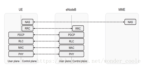
Packet Data Convergence Protocol (PDCP):
performs IP header compression to reduce the number of bits to transmit over the radio interface.
Radio-Link Control (RLC) :
is responsible for segmentation/concatenation, retransmission handling, duplicate detection, and in-sequence delivery to higher layers.
Medium-Access Control (MAC) :
handles multiplexing of logical channels, hybrid-ARQ retransmissions, and uplink and downlink scheduling.
Physical Layer (PHY) :
handles coding/decoding, modulation/demodulation, multi-antenna mapping, and other typical physical-layer functions. The physical layer offers services to the MAC layer in the form of transport channels.
1.2 More detailed overview
Downlink is illustrated here
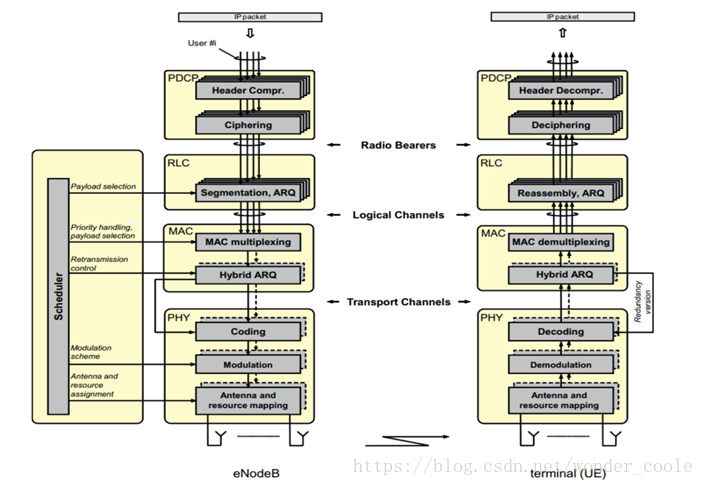
Physical channels:
These are transmission channels that carry user data and control messages.
Transport channels:
The physical layer transport channels offer information transfer to Medium Access Control (MAC) and higher layers.
Logical channels:
Provide services for the Medium Access Control (MAC) layer within the LTE protocol structure.
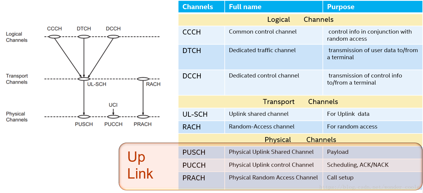
1.3 LTE Uplink Channel Mapping
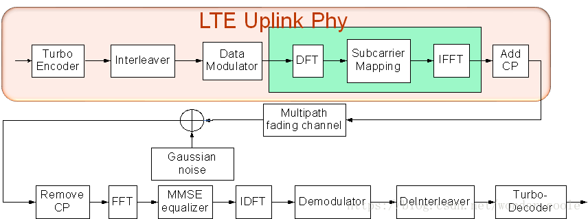
1.4 LTE uplink transmission in physical layer
LTE uplink transmission scheme is based on DFT-spread OFDM, is also called Single Carrier-FDMA(SC-FDMA).
1.5 Phy Layer’s Relation VS other layers
The physical layer interfaces the Medium Access Control (MAC) sub-layer of Layer 2 and the Radio Resource Control (RRC) Layer of Layer 3.
Logical channels
: content, such as data, voice
Transport channels
: format, such as coding method, modulation type, cp length and also
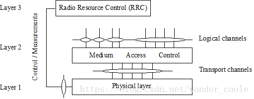
1.5.1 Layer 1 overview
1. Multiple Access
TX: SCFDMA; RX: OFDMA
Duplex : FDD/TDD(full duplex, half duplex)
Signal bandwidth/ frame structure determined by multiple access method
2.Physical channels and modulation
TX channel : PRACH, PUSCH, PUCCH
TX modulation : QPSK, 16QAM, 64QAM, 256QAM
3.Channel coding and interleaving
Turbo Coding with a coding rate of R=1/3, two 8-state constituent encoders
turbo code internal interleaver
24 bit CRC with max block of 6144 bits
4.Physical layer procedure
Cell search, power control, uplink synchronisation and uplink timing control, random access/HARQ/relay/ProSe related procedures, channel access procedure
5.Physical layer measurement
based on Radio characeristics
1.6 LTE Frame Type
1.6.1 FDD Frame Structure
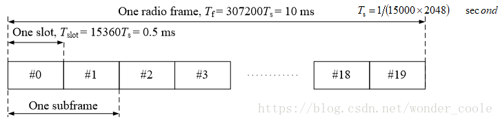
20 slots; 10 subframe; subframe I consists of slots 2i and 2i+2
Subframe ID (absolute number) :
:nf is the system frame number
10 subframes/1 frame for DL transmission and 10 subframes/1 frame for UL transmission
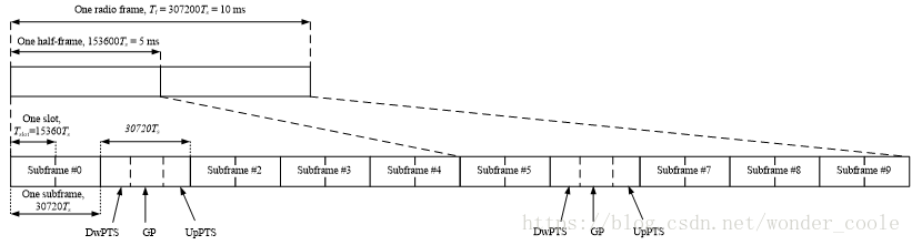
1.6.2TDD Frame Structure
|
|
|
|
|||||||||
|
|
|
|
|
|
|
|
|
|
|
||
|
|
|
|
|
|
|
|
|
|
|
|
|
|
|
|
|
|
|
|
|
|
|
|
|
|
|
|
|
|
|
|
|
|
|
|
|
|
|
|
|
|
|
|
|
|
|
|
|
|
|
|
|
|
|
|
|
|
|
|
|
|
|
|
|
|
|
|
|
|
|
|
|
|
|
|
|
|
|
|
|
|
|
|
|
|
|
|
|
|
|
1.6.3 Slot structure-Uplink resource grid
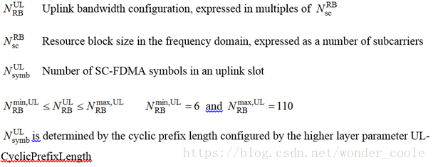

1.6.4 Resource
blocks/
Narrowbands
definition
Resource Blocks
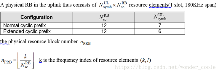
Narrowbands
1.7 UpLink channels
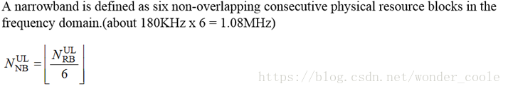
1.71 Physical uplink shared channel(PUSC)
– scrambling
– modulation of scrambled bits to generate complex-valued symbols
– mapping of the complex-valued modulation symbols onto one or several transmission layers
– transform precoding to generate complex-valued symbols
– precoding of the complex-valued symbols
– mapping of precoded complex-valued symbols to resource elements
– generation of complex-valued time-domain SC-FDMA signal for each antenna port
Scrambling
The number bits of output is same with input, bit rate is not changed
scrambling sequence generator: TBD

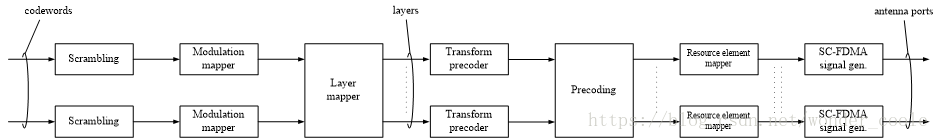
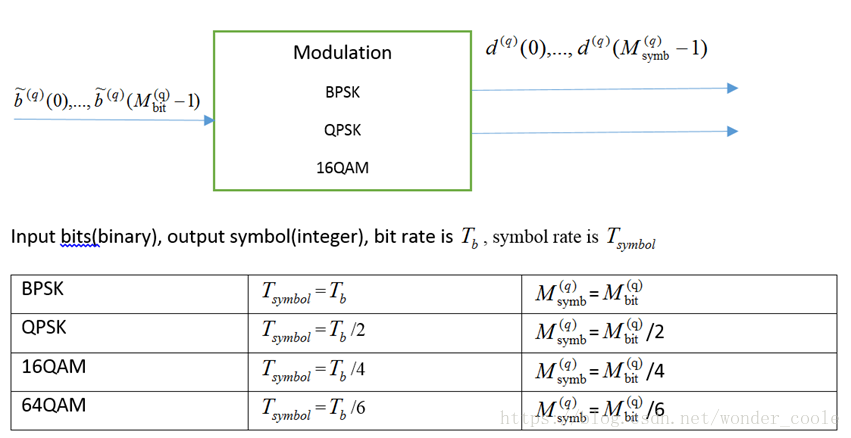
Modulation
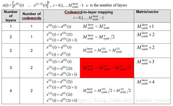
Layer mapping
1. Input is vector, output is matrix or vector
2. The case of a single codeword mapped to multiple layers is only applicable when the number of antenna ports used for PUSCH is four.
3. Layer v <= antenna port number p
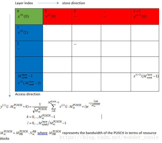
Transform
precoding
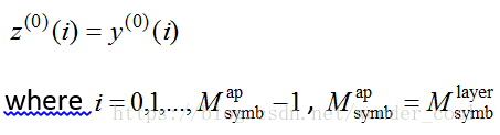
Precoding for transmission on a single antenna port
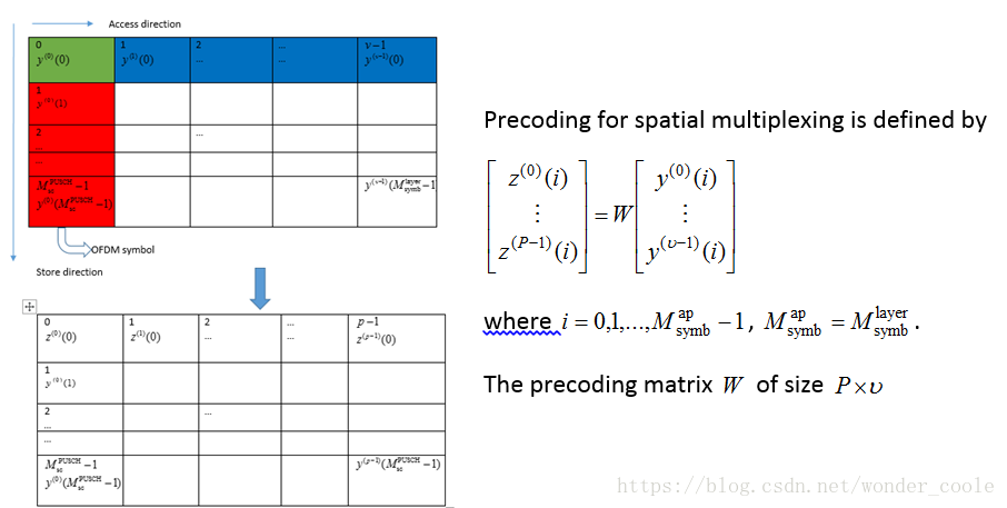
Precoding for spatial multiplexing
SC-FDMA baseband signal generation
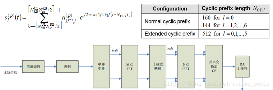
1.8 LTE Uplink Phy Digital Part
Provides all functions for an LTE uplink except digital frontend functionality, D/A conversion and RF.
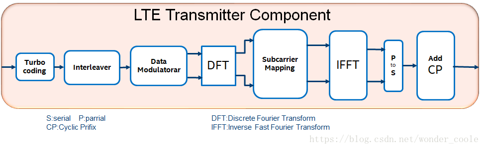
• Transport block encoding including CRC attachment(s) and rate matching
• Channel interleaving and control information multiplexing
• Scrambling and QAM mapping
• DFT transform precoding
• Reference symbol generation
• Symbol mapping in frequency domain
• IFFT including phase rotation (the latter for post-fix instead of prefix generation)
• Post-fix generation
• Gain and frequency offset application
• PUCCH generation
• Upsampling for PRACH sequence generation
• Convolutional encoding and rate matching
1.9 3GPP Documents
physical layer specifications, i.e. TS 36.200 series
Layers 2 and 3 are described in the 36.300 series
RF processing aspects are specified in the TS 36.100 series
the abbreviations given in TR 21.905
本博客所有文章均同步发表于
www.mx1980.cn/blog