首先写出Verilog代码如下:
//////////////////// 串入并出移位寄存器  /////////////////////////
module shift_reg_SIPO(
  RST   ,   // 异步复位, 高有效
  CLK   ,   // 时钟,上升沿有效
  EN    ,   // 输入数据串行移位使能
  IN    ,   // 输入串行数据
  OUT   ,  // 并行输出数据
  DIR);  // 方向选择,DIR=1时左移,DIR=0时右移
parameter SHLEN = 6;
input RST, CLK, EN;
input IN,DIR;
output[SHLEN-1:0] OUT;
reg [SHLEN-1:0] shift_R;

assign OUT[SHLEN-1:0] = shift_R[SHLEN-1:0];
// 时序逻辑 根据输入使能进行串行移位
// shift_R 会被编译为D触发器
always @ (posedge CLK or posedge RST) begin
  if(RST)
    shift_R[SHLEN-1:0] <= 0;
  else
    if(EN&&DIR) begin // 串行移位的使能有效,左移
      shift_R[SHLEN-1:1] <= shift_R[SHLEN-2:0];
      shift_R[0] <= IN;
    end
	else if(EN==1&&DIR==0) begin  // 串行移位的使能有效,右移
	  shift_R[SHLEN-2:0] <=shift_R[SHLEN-1:1];
	  shift_R[SHLEN-1] <= IN;
	end

    else begin // 使能无效保持不动
      shift_R[SHLEN-1:0] <= shift_R[SHLEN-1:0];
    end
end // always
endmodule

//////////////////// 时间基准计数器  /////////////////////////
module cnt_sync(
  CLK   ,   // clock
  CNTVAL,   // counter value
  OV    );  // overflow
input CLK;
output [32-1:0] CNTVAL;
output OV;
parameter MAX_VAL = 25_000_000;
reg [32-1:0] CNTVAL;
reg OV;

always @ (posedge CLK) begin
  if(CNTVAL >= MAX_VAL)
    CNTVAL <= 0;
  else
    CNTVAL <= CNTVAL + 1'b1;
end

always @ (CNTVAL) begin
  if(CNTVAL == MAX_VAL)
    OV = 1'b1;
  else
    OV = 1'b0;
end

endmodule   // module cnt_en_0to9
////////////////////////////////////////////////////////////////////////////////
bdf原理图:
编译后,设置引脚,记住不用的引脚设为三态,
RTL Viewer:

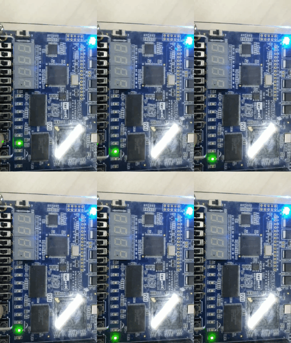
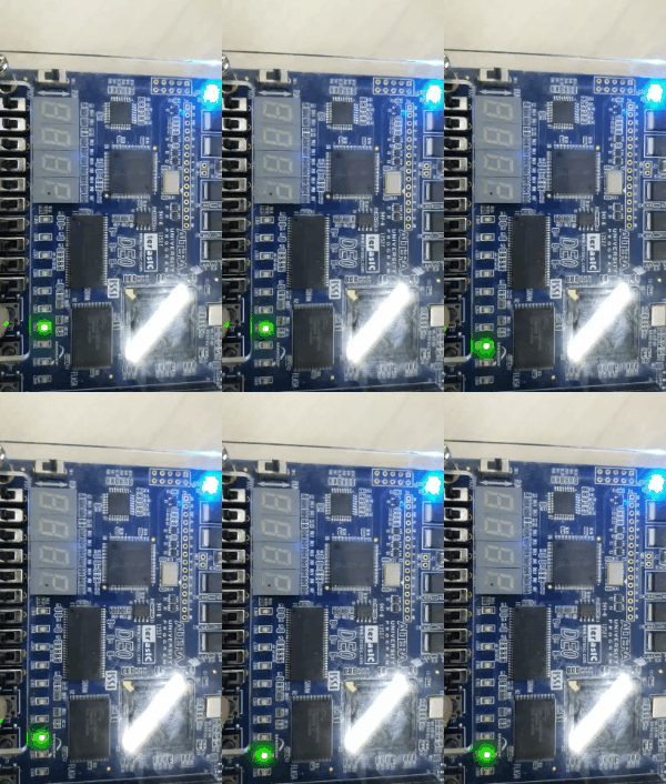
编译下载后:
右移

左移:

验证了实验的正确性。
版权声明:本文为Python_banana原创文章,遵循 CC 4.0 BY-SA 版权协议,转载请附上原文出处链接和本声明。

