一、目的
相信最开始玩过STM32f103开发的同学一般都是从看芯片手册或者开发手册看起的,有时候要配置一个时钟或者IO管脚都要花上很长时间。初学者一般第一个工程都是从别人那边准备好的模板工程开始学习,然后才逐渐开始自己从零创建自己的第一个模板工程。
为了解决此类繁琐枯燥的工作,ST为我们提供了STM32CubeMX工具,有了这个工具,我们就可以分分钟创建一个demo工程。
下面我们以STM32H750XBH6_ArtPi开发板为例,指导初学者使用这个工具。
(STM32H750XBH6_ArtPi开发板是由瑞赛德开源的开发板,也就是大家熟知的国产嵌入式操作系统rtthread)
二、准备
STM32CubeMX V6.3.0
Keil MDK以及对应的STM32H750 PACK软件(如何下载安装请自行百度)
三、实战
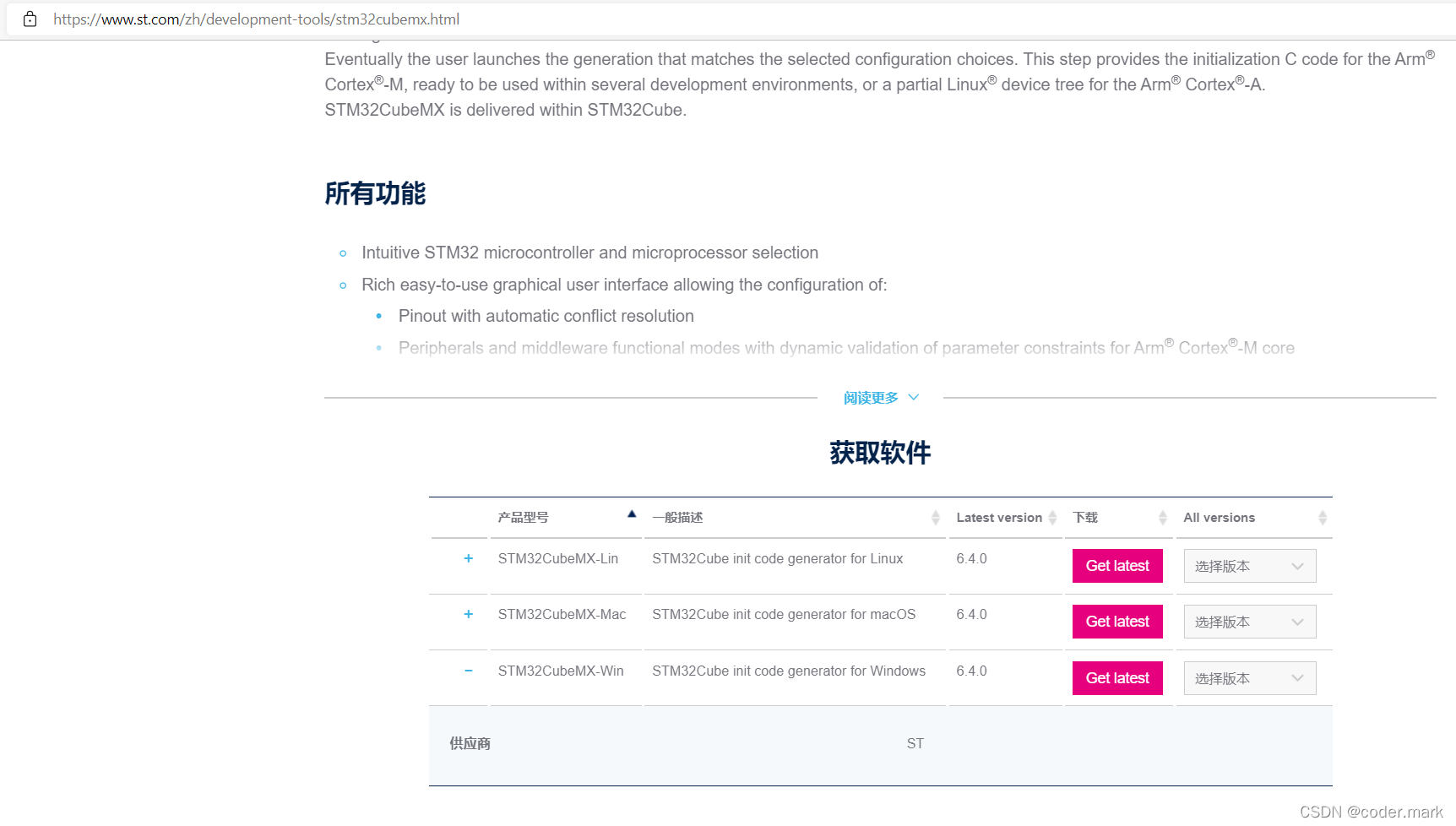
1、首先我们去ST官网下载STM32CubeMX。

使用什么平台就下载对应平台的安装包,建议使用Windows版本。
2、安装(安装路径可以自定义)
一直选择同意就行
3、运行STM32CubeMX

选择右边的INSTALL/REMOVE下载需要pack,我们的芯片是STM32H750XBH6。

选择STM21H7,然后点击安装。
4、创建工程
我们创建一个最简单的工程为例,将开发板上的LED交替闪烁,STM32H750XBH6_ArtPi开发板板载连个RED/BLUE两个LED。
点击File–New Project创建新的工程
在Part Number中输入stm32h750xbh6后选中就可以点击创建新的工程(Start Project)。

配置RCC,即配置时钟输入相关参数

开发板使用25MHz的外部晶振
配置GPIO


从电路图上看IO为PC15、PI8,我们只需要设置为输出口,并且为低电平时,LED就会亮。

配置时钟

在Project Manager里面设置相关参数
我们选择Toolchain/IDE为MDK-ARM,这样我们就可以用Keil进行开发调试了。

Code Generator设置如下

点击右上角的GENERATE CODE

我们打开我们已经创建好的工程

在开始添加代码之前我们可以先直接编译一下工程。

可以发现可以正常的编译通过。
在main.c里面添加如下代码

/* USER CODE BEGIN Header */
/**
******************************************************************************
* @file : main.c
* @brief : Main program body
******************************************************************************
* @attention
*
* <h2><center>© Copyright (c) 2021 STMicroelectronics.
* All rights reserved.</center></h2>
*
* This software component is licensed by ST under BSD 3-Clause license,
* the "License"; You may not use this file except in compliance with the
* License. You may obtain a copy of the License at:
* opensource.org/licenses/BSD-3-Clause
*
******************************************************************************
*/
/* USER CODE END Header */
/* Includes ------------------------------------------------------------------*/
#include "main.h"
/* Private includes ----------------------------------------------------------*/
/* USER CODE BEGIN Includes */
/* USER CODE END Includes */
/* Private typedef -----------------------------------------------------------*/
/* USER CODE BEGIN PTD */
/* USER CODE END PTD */
/* Private define ------------------------------------------------------------*/
/* USER CODE BEGIN PD */
/* USER CODE END PD */
/* Private macro -------------------------------------------------------------*/
/* USER CODE BEGIN PM */
/* USER CODE END PM */
/* Private variables ---------------------------------------------------------*/
/* USER CODE BEGIN PV */
/* USER CODE END PV */
/* Private function prototypes -----------------------------------------------*/
void SystemClock_Config(void);
static void MX_GPIO_Init(void);
/* USER CODE BEGIN PFP */
/* USER CODE END PFP */
/* Private user code ---------------------------------------------------------*/
/* USER CODE BEGIN 0 */
/* USER CODE END 0 */
/**
* @brief The application entry point.
* @retval int
*/
int main(void)
{
/* USER CODE BEGIN 1 */
/* USER CODE END 1 */
/* MCU Configuration--------------------------------------------------------*/
/* Reset of all peripherals, Initializes the Flash interface and the Systick. */
HAL_Init();
/* USER CODE BEGIN Init */
/* USER CODE END Init */
/* Configure the system clock */
SystemClock_Config();
/* USER CODE BEGIN SysInit */
/* USER CODE END SysInit */
/* Initialize all configured peripherals */
MX_GPIO_Init();
/* USER CODE BEGIN 2 */
/* USER CODE END 2 */
/* Infinite loop */
/* USER CODE BEGIN WHILE */
while (1)
{
/* USER CODE END WHILE */
/* USER CODE BEGIN 3 */
HAL_GPIO_TogglePin(GPIOC, GPIO_PIN_15);
HAL_Delay(500);
HAL_GPIO_TogglePin(GPIOC, GPIO_PIN_15);
HAL_GPIO_TogglePin(GPIOI, GPIO_PIN_8);
HAL_Delay(500);
HAL_GPIO_TogglePin(GPIOI, GPIO_PIN_8);
}
/* USER CODE END 3 */
}
/**
* @brief System Clock Configuration
* @retval None
*/
void SystemClock_Config(void)
{
RCC_OscInitTypeDef RCC_OscInitStruct = {0};
RCC_ClkInitTypeDef RCC_ClkInitStruct = {0};
/** Supply configuration update enable
*/
HAL_PWREx_ConfigSupply(PWR_LDO_SUPPLY);
/** Configure the main internal regulator output voltage
*/
__HAL_PWR_VOLTAGESCALING_CONFIG(PWR_REGULATOR_VOLTAGE_SCALE0);
while(!__HAL_PWR_GET_FLAG(PWR_FLAG_VOSRDY)) {}
/** Initializes the RCC Oscillators according to the specified parameters
* in the RCC_OscInitTypeDef structure.
*/
RCC_OscInitStruct.OscillatorType = RCC_OSCILLATORTYPE_HSE;
RCC_OscInitStruct.HSEState = RCC_HSE_ON;
RCC_OscInitStruct.PLL.PLLState = RCC_PLL_ON;
RCC_OscInitStruct.PLL.PLLSource = RCC_PLLSOURCE_HSE;
RCC_OscInitStruct.PLL.PLLM = 5;
RCC_OscInitStruct.PLL.PLLN = 192;
RCC_OscInitStruct.PLL.PLLP = 2;
RCC_OscInitStruct.PLL.PLLQ = 2;
RCC_OscInitStruct.PLL.PLLR = 2;
RCC_OscInitStruct.PLL.PLLRGE = RCC_PLL1VCIRANGE_2;
RCC_OscInitStruct.PLL.PLLVCOSEL = RCC_PLL1VCOWIDE;
RCC_OscInitStruct.PLL.PLLFRACN = 0;
if (HAL_RCC_OscConfig(&RCC_OscInitStruct) != HAL_OK)
{
Error_Handler();
}
/** Initializes the CPU, AHB and APB buses clocks
*/
RCC_ClkInitStruct.ClockType = RCC_CLOCKTYPE_HCLK|RCC_CLOCKTYPE_SYSCLK
|RCC_CLOCKTYPE_PCLK1|RCC_CLOCKTYPE_PCLK2
|RCC_CLOCKTYPE_D3PCLK1|RCC_CLOCKTYPE_D1PCLK1;
RCC_ClkInitStruct.SYSCLKSource = RCC_SYSCLKSOURCE_PLLCLK;
RCC_ClkInitStruct.SYSCLKDivider = RCC_SYSCLK_DIV1;
RCC_ClkInitStruct.AHBCLKDivider = RCC_HCLK_DIV2;
RCC_ClkInitStruct.APB3CLKDivider = RCC_APB3_DIV2;
RCC_ClkInitStruct.APB1CLKDivider = RCC_APB1_DIV2;
RCC_ClkInitStruct.APB2CLKDivider = RCC_APB2_DIV2;
RCC_ClkInitStruct.APB4CLKDivider = RCC_APB4_DIV2;
if (HAL_RCC_ClockConfig(&RCC_ClkInitStruct, FLASH_LATENCY_4) != HAL_OK)
{
Error_Handler();
}
}
/**
* @brief GPIO Initialization Function
* @param None
* @retval None
*/
static void MX_GPIO_Init(void)
{
GPIO_InitTypeDef GPIO_InitStruct = {0};
/* GPIO Ports Clock Enable */
__HAL_RCC_GPIOC_CLK_ENABLE();
__HAL_RCC_GPIOI_CLK_ENABLE();
__HAL_RCC_GPIOH_CLK_ENABLE();
/*Configure GPIO pin Output Level */
HAL_GPIO_WritePin(GPIOC, GPIO_PIN_15, GPIO_PIN_SET);
/*Configure GPIO pin Output Level */
HAL_GPIO_WritePin(GPIOI, GPIO_PIN_8, GPIO_PIN_SET);
/*Configure GPIO pin : PC15 */
GPIO_InitStruct.Pin = GPIO_PIN_15;
GPIO_InitStruct.Mode = GPIO_MODE_OUTPUT_PP;
GPIO_InitStruct.Pull = GPIO_PULLUP;
GPIO_InitStruct.Speed = GPIO_SPEED_FREQ_LOW;
HAL_GPIO_Init(GPIOC, &GPIO_InitStruct);
/*Configure GPIO pin : PI8 */
GPIO_InitStruct.Pin = GPIO_PIN_8;
GPIO_InitStruct.Mode = GPIO_MODE_OUTPUT_PP;
GPIO_InitStruct.Pull = GPIO_PULLUP;
GPIO_InitStruct.Speed = GPIO_SPEED_FREQ_LOW;
HAL_GPIO_Init(GPIOI, &GPIO_InitStruct);
}
/* USER CODE BEGIN 4 */
/* USER CODE END 4 */
/**
* @brief This function is executed in case of error occurrence.
* @retval None
*/
void Error_Handler(void)
{
/* USER CODE BEGIN Error_Handler_Debug */
/* User can add his own implementation to report the HAL error return state */
__disable_irq();
while (1)
{
}
/* USER CODE END Error_Handler_Debug */
}
#ifdef USE_FULL_ASSERT
/**
* @brief Reports the name of the source file and the source line number
* where the assert_param error has occurred.
* @param file: pointer to the source file name
* @param line: assert_param error line source number
* @retval None
*/
void assert_failed(uint8_t *file, uint32_t line)
{
/* USER CODE BEGIN 6 */
/* User can add his own implementation to report the file name and line number,
ex: printf("Wrong parameters value: file %s on line %d\r\n", file, line) */
/* USER CODE END 6 */
}
#endif /* USE_FULL_ASSERT */
/************************ (C) COPYRIGHT STMicroelectronics *****END OF FILE****/
再次编译通过,我们配置调试器进行下载。
配置调试器和下载器,点击Debug选项卡选择ST-Link Debugger,然后点击Settings


点击Utilities->Settings

按图设置

点击下载即可
