前言
众所周知,STC89C52RC有一个定时器2,具体的不说了,你只需要知道本文是将它用来产生串口波特率从而进行串口通信的定时器就对了。
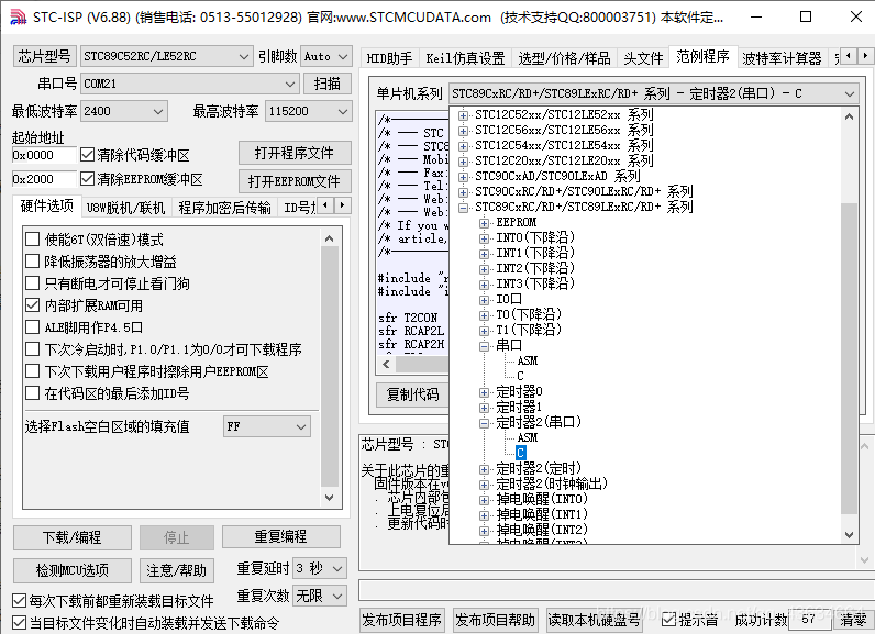
声明:本文代码是在STC提供的范例程序基础上进行修改,程序在STC官方工具STC-ISP软件里。

但因为范例程序是收一个字节展示一个字节,也就是在P0和P2.2上表示出收到的内容,而我们需要的是
收到字符串消息处理后再xxx
,重点是能收到字符串,当然,这也很简单,但不懂为什么我调试了贼久。
思路就是:每次收到一个字节,就从SBUF读取该字节并加入字符数组buff,最后在处理过程中,将这个数组拷贝给另一个长度比它大1的数组str,并追加’\0’。
没办法,我之前遇到的问题就是,假设它收到字符串后,buff[]里面的东西处理完了,没法清空,试了memset(buff, ‘\0’, sizeof(buff))、也试了for循环赋值’\0’,但很奇怪居然失效了,如果有试成功的可以告诉我。
通常来讲,判断是否收完一个字符串内容有定时器方法、标志位方法,这里我用的是第二种,因为51单片机定时器本来就少,定时器0我用来延时了,定时器1我准备用来做软件定时器。
一、宏定义
#define FOSC 11059200L      // 晶振
#define BAUD 115200       	// 波特率

/*Define UART parity mode*/
#define NONE_PARITY     0   // 无校验位
#define ODD_PARITY      1   // 奇校验位
#define EVEN_PARITY     2   // 偶校验位
#define MARK_PARITY     3   // 校验位始终为1
#define SPACE_PARITY    4   // 校验位始终为0

#define PARITYBIT NONE_PARITY

#define MAXSIZE_BUFF	16
二、变量
bit busy;

static unsigned int count = 0;

bit flag_receive_finish = 0;

char buff[MAXSIZE_BUFF] = {0};
三、函数
/**
 * **************************************************
 * @brief main
 * **************************************************
 */
int main(void) {
	EA = 1;
	init_uart();
	while(1) {
		if (0 != flag_receive_finish) {
			receive_process();
		}
	}
}
/*----------------------------
Process data after receiving message
Input:None
Output:None
----------------------------*/
void receive_process() {
	char str[MAXSIZE_BUFF + 1] = {0};
	unsigned int i;
	for (i = 0; i < count; i++) {
		str[i] = buff[i];
	}
	str[i] = '\0';
	SendString(str);
	memset(buff, '\0', sizeof(buff));
	count = 0;
	flag_receive_finish = 0;
}
/*----------------------------
UART interrupt service routine
----------------------------*/
void Uart_Isr() interrupt 4 {
	if (RI) {
		RI = 0;             //Clear receive interrupt flag
		if (0 == flag_receive_finish) {
			if ('$' == SBUF) {
				flag_receive_finish = 1;
			} else {
				buff[count++] = SBUF;
			}
		}
		if (MAXSIZE_BUFF == count) {
			flag_receive_finish = 1;
		}
	}

	if (TI) {
		TI = 0;             //Clear transmit interrupt flag
		busy = 0;           //Clear transmit busy flag
	}
}
下面是STC官方的例程里提供的串口发送函数和串口初始化。
/*----------------------------
UART init
----------------------------*/
void init_uart() {
	count = 0;
	flag_receive_finish = 0;

#if (PARITYBIT == NONE_PARITY)
	SCON = 0x50;            //8-bit variable UART
#elif (PARITYBIT == ODD_PARITY) || (PARITYBIT == EVEN_PARITY) || (PARITYBIT == MARK_PARITY)
	SCON = 0xda;            //9-bit variable UART, parity bit initial to 1
#elif (PARITYBIT == SPACE_PARITY)
	SCON = 0xd2;            //9-bit variable UART, parity bit initial to 0
#endif

	TL2 = RCAP2L = (65536 - (FOSC / 32 / BAUD));
	TH2 = RCAP2H = (65536 - (FOSC / 32 / BAUD)) >> 8;
	T2CON = 0x34;
	ES = 1;
	EA = 1;
}
/*----------------------------
Send a byte data to UART
Input: dat (data to be sent)
Output:None
----------------------------*/
void SendData(unsigned char dat) {
	while (busy);           //Wait for the completion of the previous data is sent
	ACC = dat;              //Calculate the even parity bit P (PSW.0)
	if (P) {                //Set the parity bit according to P
#if (PARITYBIT == ODD_PARITY)
		TB8 = 0;            //Set parity bit to 0
#elif (PARITYBIT == EVEN_PARITY)
		TB8 = 1;            //Set parity bit to 1
#endif
	} else {
#if (PARITYBIT == ODD_PARITY)
		TB8 = 1;            //Set parity bit to 1
#elif (PARITYBIT == EVEN_PARITY)
		TB8 = 0;            //Set parity bit to 0
#endif
	}
	busy = 1;
	SBUF = ACC;             //Send data to UART buffer
}
/*----------------------------
Send a string to UART
Input: s (address of string)
Output:None
----------------------------*/
void SendString(char *s) {
	while (*s) {            //Check the end of the string
		SendData(*s++);     //Send current char and increment string ptr
	}
}
四、结果
上面的代码应该很好理解吧,就是开头思路说的,设一个标志位(这里用的是
&
),如果超过长度或者遇到标志位则停止接收,把收到的这一串复制给新串,发送后清空原串(其实清不清无所谓,因为count从0计数了),最后把这新串添加’\0’通过串口再发送出去。
如图:
这里设置的是16位存储,所以如果没有遇到标志符,那么直到16位满了才接收完一次。

但如果遇到标识符’$’,则立刻停止接收。

问题是没有问题了的,不过我后续还得做其他东西,51只是作为指令接收机,也就是下位机,上位机还是得用STM32做?。
END