AHT10温湿度传感器
概念
传感器输出经过标定的数字信号输出,通过标准的I2C接口传输数据;
相对湿度的分辨率在
0.024%RH
,工作范围为
0~100%RH
;
温度值的分辨率在
0.01℃
,工作范围为
-40~85℃
;
AHT10的供电范围为
1.8~3.6V
,推荐使用
3.3V
供电;
接口包含了完全静态逻辑,因而不存在最小串行时钟SCL频率;
IIC协议,同步半双工通信协议
起始位
:主机在时钟高电平期间拉低总线;
数据位
:主机在时钟低电平期间发送数据,主机在高电平期间保持不变;从机在时钟高电平期间采样数据;
应答为
:主机收到数据后发送应答,从机才会发送下一字节数据;
停止位
:主机在时钟高电平期间释放总线,主机在低电平期间保持不变;
- 可使用的I2C通信模式有经典型和高速模式,经典模式最小时钟周期是250us,高速模式最小时钟周期是100us;
AHT10配置与通信
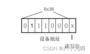
I2C通信通过设备地址与从机进行通信,

-
首先上电启动传感器,启动后需要先等待40ms(设备才开始正常工作),然后发送
8‘h71
来获取状态字节,状态寄存器说明如下:

获取到校准使能位后,查看其是否已校准,若已校准则跳过当前步骤;若未校准则发送
8‘hE1
,进行初始化,然后发送
8’h08
,
8‘h00
; -
接着开始触发测量,测量先发送
8’hAC
,然后发送
8‘h33
,
8'h00
; -
测量命令发送完成后,需要等待80ms,用于温湿度的测量;之后再发送命令
8‘h71
,以读取状态寄存器是否处于空闲状态(
bit7 => idle
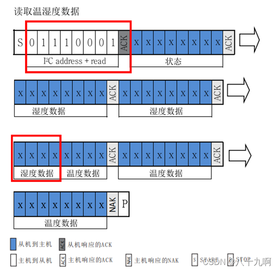
);若是空闲状态,可以直接读取之后六个字节的温湿度数值; -
读取温湿度数据构成

-
相对湿度和温度转换公式
将接收到的湿度值转换成%RH的格式:
RH
[
%
]
=
(
S
R
H
/
2
20
)
RH [\%] = (SRH/2^{20})
R
H
[
%
]
=
(
SR
H
/
2
20
)
温度转换成℃表示:
T(
℃
)
=
(
S
T
/
2
20
)
.
T(℃) = (ST/2^{20}).
T
(
℃
)
=
(
ST
/
2
20
)
.
设计框架
-
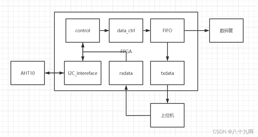
整个模块的设计,首先是上位机通过UART,发送命令打开AHT10驱动控制模块、数码管显示模块以及串口模块;设备驱动用控制模块实现,通信接口使用I2C与AHT10进行通信,然后将读取的温湿度值先进行数值转换并取整,并转换成ASCII码方便查看温湿度值;然后将数据缓存到FIFO中,当缓存了一组完整的温度值数据后进行输出,发送给上位机,或是直接通过数码管显示;

I2C模块

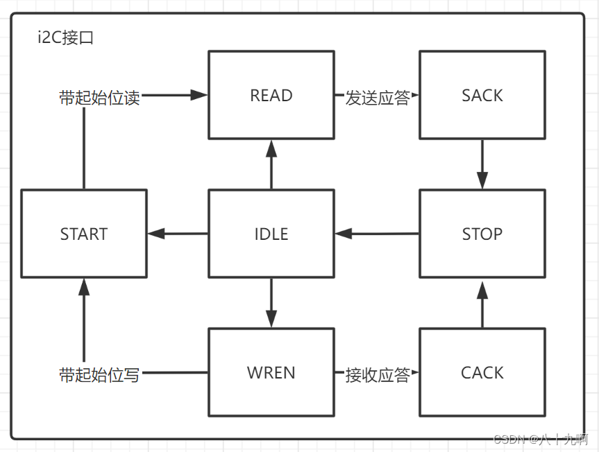
I2C接口模块状态机如上图所示,从空闲状态可以先发送起始位再读写一个字节数据,或直接读写一个字节数据,然后是收发应答位;最后发送停止位,就完成了一组数据的读写;
对于I2C通信,数据的传输速率选择的是
50M/250 Bps
;
include "param.v"
module i2c_master(
    input               clk         ,
    input               rst_n       ,
    input               req         ,
    input       [3:0]   cmd         ,
    input       [7:0]   din         ,
    output      [7:0]   dout        ,
    output              done        ,
    output              slave_ack   ,
    output              i2c_scl     ,
    input               i2c_sda_i   ,
    output              i2c_sda_o   ,
    output              i2c_sda_oe
    );

//状态机参数定义
localparam  IDLE  = 7'b000_0001,
            START = 7'b000_0010,
            WRITE = 7'b000_0100,
            RACK  = 7'b000_1000,
            READ  = 7'b001_0000,
            SACK  = 7'b010_0000,
            STOP  = 7'b100_0000;
//
    reg     [6:0]       state_c     ;
    reg     [6:0]       state_n     ;
    reg     [8:0]       cnt_scl     ;//产生i2c时钟
    wire                add_cnt_scl ;
    wire                end_cnt_scl ;
    reg     [3:0]       cnt_bit     ;//传输数据 bit计数器
    wire                add_cnt_bit ;
    wire                end_cnt_bit ;
    reg     [3:0]       bit_num     ;
    reg                 scl         ;//输出寄存器
    reg                 sda_out     ;
    reg                 sda_out_en  ;
    reg     [7:0]       rx_data     ;
    reg                 rx_ack      ;
    reg     [3:0]       command     ;
    reg     [7:0]       tx_data     ;//发送数据

    wire                idle2start  ;
    wire                idle2write  ;
    wire                idle2read   ;
    wire                start2write ;
    wire                start2read  ;
    wire                write2rack  ;
    wire                read2sack   ;
    wire                rack2stop   ;
    wire                sack2stop   ;
    wire                rack2idle   ;
    wire                sack2idle   ;
    wire                stop2idle   ;


//状态机
    always @(posedge clk or negedge rst_n) begin
        if (rst_n==0) begin
            state_c <= IDLE ;
        end
        else begin
            state_c <= state_n;
       end
    end

    always @(*) begin
        case(state_c)
            IDLE :begin
                if(idle2start)
                    state_n = START ;
                else if(idle2write)
                    state_n = WRITE ;
                else if(idle2read)
                    state_n = READ ;
                else
                    state_n = state_c ;
            end
            START :begin
                if(start2write)
                    state_n = WRITE ;
                else if(start2read)
                    state_n = READ ;
                else
                    state_n = state_c ;
            end
            WRITE :begin
                if(write2rack)
                    state_n = RACK ;
                else
                    state_n = state_c ;
            end
            RACK :begin
                if(rack2stop)
                    state_n = STOP ;
                else if(rack2idle)
                    state_n = IDLE ;
                else
                    state_n = state_c ;
            end
            READ :begin
                if(read2sack)
                    state_n = SACK ;
                else
                    state_n = state_c ;
            end
            SACK :begin
                if(sack2stop)
                    state_n = STOP ;
                else if(sack2idle)
                    state_n = IDLE ;
                else
                    state_n = state_c ;
            end
            STOP :begin
                if(stop2idle)
                    state_n = IDLE ;
                else
                    state_n = state_c ;
            end
            default : state_n = IDLE ;
        endcase
    end

    assign idle2start  = state_c==IDLE  && (req && (cmd&`CMD_START));
    assign idle2write  = state_c==IDLE  && (req && (cmd&`CMD_WRITE));
    assign idle2read   = state_c==IDLE  && (req && (cmd&`CMD_READ ));
    assign start2write = state_c==START && (end_cnt_bit && (command&`CMD_WRITE));
    assign start2read  = state_c==START && (end_cnt_bit && (command&`CMD_READ ));
    assign write2rack  = state_c==WRITE && (end_cnt_bit);
    assign read2sack   = state_c==READ  && (end_cnt_bit);
    assign rack2stop   = state_c==RACK  && (end_cnt_bit && (command&`CMD_STOP ));
    assign sack2stop   = state_c==SACK  && (end_cnt_bit && (command&`CMD_STOP ));
    assign rack2idle   = state_c==RACK  && (end_cnt_bit && (command&`CMD_STOP ) == 0);
    assign sack2idle   = state_c==SACK  && (end_cnt_bit && (command&`CMD_STOP ) == 0);
    assign stop2idle   = state_c==STOP  && (end_cnt_bit);

//计数器
    always @(posedge clk or negedge rst_n) begin
        if (rst_n==0) begin
            cnt_scl <= 0;
        end
        else if(add_cnt_scl) begin
            if(end_cnt_scl)
                cnt_scl <= 0;
            else
                cnt_scl <= cnt_scl+1 ;
       end
    end
    assign add_cnt_scl = (state_c != IDLE);
    assign end_cnt_scl = add_cnt_scl  && cnt_scl == (`SCL_PERIOD)-1 ;

    always @(posedge clk or negedge rst_n) begin
        if (rst_n==0) begin
            cnt_bit <= 0;
        end
        else if(add_cnt_bit) begin
            if(end_cnt_bit)
                cnt_bit <= 0;
            else
                cnt_bit <= cnt_bit+1 ;
       end
    end
    assign add_cnt_bit = (end_cnt_scl);
    assign end_cnt_bit = add_cnt_bit  && cnt_bit == (bit_num)-1 ;

    always  @(*)begin
        if(state_c == WRITE | state_c == READ) begin
            bit_num = 8;
        end
        else begin
            bit_num = 1;
        end
    end
//command
    always  @(posedge clk or negedge rst_n)begin
        if(~rst_n)begin
            command <= 0;
        end
        else if(req)begin
            command <= cmd;
        end
    end

//tx_data
    always  @(posedge clk or negedge rst_n)begin
        if(~rst_n)begin
            tx_data <= 0;
        end
        else if(req)begin
            tx_data <= din;
        end
    end

//scl
    always  @(posedge clk or negedge rst_n)begin
        if(~rst_n)begin
            scl <= 1'b1;
        end
        else if(idle2start | idle2write | idle2read)begin//开始发送时,拉低
            scl <= 1'b0;
        end
        else if(add_cnt_scl && cnt_scl == `SCL_HALF-1)begin
            scl <= 1'b1;
        end
        else if(end_cnt_scl && ~stop2idle)begin
            scl <= 1'b0;
        end
    end

//sda_out
    always  @(posedge clk or negedge rst_n)begin
        if(~rst_n)begin
            sda_out <= 1'b1;
        end
        else if(state_c == START)begin          //发起始位
            if(cnt_scl == `LOW_HLAF)begin       //时钟低电平时拉高sda总线
                sda_out <= 1'b1;
            end
            else if(cnt_scl == `HIGH_HALF)begin    //时钟高电平时拉低sda总线
                sda_out <= 1'b0;                //保证从机能检测到起始位
            end
        end
        else if(state_c == WRITE && cnt_scl == `LOW_HLAF)begin  //scl低电平时发送数据   并串转换
            sda_out <= tx_data[7-cnt_bit];
        end
        else if(state_c == SACK && cnt_scl == `LOW_HLAF)begin  //发应答位
            sda_out <= (command&`CMD_STOP)?1'b1:1'b0;
        end
        else if(state_c == STOP)begin //发停止位
            if(cnt_scl == `LOW_HLAF)begin       //时钟低电平时拉低sda总线
                sda_out <= 1'b0;
            end
            else if(cnt_scl == `HIGH_HALF)begin    //时钟高电平时拉高sda总线
                sda_out <= 1'b1;                //保证从机能检测到停止位
            end
        end
    end

//sda_out_en  总线输出数据使能
    always  @(posedge clk or negedge rst_n)begin
        if(~rst_n)begin
            sda_out_en <= 1'b0;
        end
        else if(idle2start | idle2write | read2sack | rack2stop)begin
            sda_out_en <= 1'b1;
        end
        else if(idle2read | start2read | write2rack | stop2idle)begin
            sda_out_en <= 1'b0;
        end
    end

//rx_data       接收读入的数据
    always  @(posedge clk or negedge rst_n)begin
        if(~rst_n)begin
            rx_data <= 0;
        end
        else if(state_c == READ && cnt_scl == `HIGH_HALF)begin
            rx_data[7-cnt_bit] <= i2c_sda_i;    //串并转换
        end
    end

//rx_ack
    always  @(posedge clk or negedge rst_n)begin
        if(~rst_n)begin
            rx_ack <= 1'b1;
        end
        else if(state_c == RACK && cnt_scl == `HIGH_HALF)begin
            rx_ack <= i2c_sda_i;
        end
    end

//输出信号
    assign i2c_scl    = scl         ;
    assign i2c_sda_o  = sda_out     ;
    assign i2c_sda_oe = sda_out_en  ;
    assign dout = rx_data;
    assign done = rack2idle | sack2idle | stop2idle;
    assign slave_ack = rx_ack;
endmodule
`include "param.v"
module aht_ctrl (
    input               	sys_clk    		,
    input               	rst_n   		,
	input					driver_en		,
    output              	req     		,
    output      [3:0]   	cmd     		,
    output      [7:0]   	data    		,
    input               	done    		,
    input       [7:0]   	rd_data 		,
    output		[19:0]		hum_data		,
    output      [19:0]		temp_data		,
    output				    dout_vld
    );

//
    localparam  START =      7'b000_0001,
                INIT =       7'b000_0010,
                CHECK_INIT = 7'b000_0100,
                IDLE =       7'b000_1000,
                TRIGGER =    7'b001_0000,
                WAIT =       7'b010_0000,
                READ =       7'b100_0000;
    parameter	DELAY_40MS = 200_0000  ,
                DELAY_80MS = 400_0000  ,
                DELAY_500MS = 2500_0000;

    reg     [7:0]   	state_c         ;
    reg     [7:0]  	 	state_n         ;
    reg     [2:0]   	cnt_byte        ;
    wire            	add_cnt_byte    ;
    wire            	end_cnt_byte    ;
    reg             	tx_req          ;
    reg     [3:0]   	tx_cmd          ;
    reg     [7:0]   	tx_data         ;
    reg		[47:0]		read_data		;
    reg		[27:0]		cnt				;
    wire				add_cnt			;
    wire				end_cnt			;
    reg		[24:0]		delay			;
    reg					finish_init		;
    wire				start2init		;
    wire				init2check		;
    wire				check2idle		;
    wire				check2init		;
    wire				idle2trigger	;
    wire				trigger2wait	;
    wire				wait2read		;
    wire				read2idle		;
	reg					driver_en_r1	;
	reg					driver_en_r2	;
	wire				ne_driver		;
// ne_driver
	always@(posedge sys_clk or negedge rst_n)begin
		if(!rst_n) begin
			driver_en_r1  <= 0 ;
			driver_en_r2  <= 0 ;
		end
		else begin
			driver_en_r1  <= driver_en ;
			driver_en_r2  <= driver_en_r1 ;
		end
	end
	assign ne_driver = (~driver_en_r1 && driver_en_r2) ;
//state
    always @(posedge sys_clk or negedge rst_n) begin
        if (rst_n==0) begin
            state_c <= START ;
        end
        else begin
            state_c <= state_n;
       end
    end
//状态转移
    always @(*) begin
        case(state_c)
            START :begin
				if(ne_driver) begin
					state_n = state_c ;
				end
				else if(start2init) begin
                    state_n = INIT ;
				end
                else begin
                    state_n = state_c ;
				end
            end
            INIT :begin
				if(ne_driver) begin
					state_n = START ;
				end
                else if(init2check)begin
                    state_n = IDLE ;
				end
                else
                    state_n = state_c ;
            end
            CHECK_INIT :begin
				if(ne_driver) begin
					state_n = START ;
				end
                else if(check2idle)begin
                    state_n = IDLE ;
				end
                else if(check2init) begin
                    state_n = INIT;
                end
                else
                    state_n = state_c ;
            end
            IDLE :begin
				if(ne_driver)begin
					state_n = START ;
				end
                else if(idle2trigger)begin
                    state_n = TRIGGER ;
				end
                else
                    state_n = state_c ;
            end
            TRIGGER :begin
				if(ne_driver)begin
					state_n = START ;
				end
                else if(trigger2wait)begin
                    state_n = WAIT ;
				end
                else
                    state_n = state_c ;
            end
            WAIT :begin
                if(ne_driver)begin
					state_n = START ;
				end
                else if(wait2read)
                    state_n = READ ;
                else
                    state_n = state_c ;
            end
            READ :begin
                if(ne_driver)begin
					state_n = START ;
				end
                else if(read2idle)
                    state_n = IDLE ;
                else
                    state_n = state_c ;
            end

            default : state_n = START ;
        endcase
    end

    assign start2init = state_c == START && (end_cnt);
    assign init2check = state_c == INIT && (end_cnt_byte);
    assign check2idle = state_c == CHECK_INIT && (finish_init) && end_cnt_byte;
    assign check2init = state_c == CHECK_INIT && (~finish_init)&& end_cnt_byte;
    assign idle2trigger = state_c == IDLE && (end_cnt);
    assign trigger2wait = state_c == TRIGGER && (end_cnt_byte);
    assign wait2read = state_c == WAIT && (end_cnt);
    assign read2idle = state_c == READ && (end_cnt_byte);

// delay
    always @(posedge sys_clk or negedge rst_n) begin
        if(!rst_n) begin
            delay <= DELAY_40MS;
        end
        else if(state_c == START) begin
            delay <= DELAY_40MS;
        end
        else if(state_c == WAIT) begin
            delay <= DELAY_80MS;
        end
        else if(state_c == IDLE) begin
            delay <= DELAY_500MS;
        end
    end

// cnt
    always @( posedge sys_clk or negedge rst_n ) begin
        if ( !rst_n ) begin
            cnt <= 0;
        end
        else if ( add_cnt ) begin
            if ( end_cnt ) begin
                cnt <= 0;
            end
            else begin
                cnt <= cnt + 1;
            end
        end
        else begin
            cnt <= 0;
        end
    end
    assign add_cnt = (state_c == START || state_c == WAIT || state_c == IDLE) && driver_en_r2;
    assign end_cnt = cnt == delay - 1 && add_cnt || ne_driver ;

// cnt_byte
    always @(posedge sys_clk or negedge rst_n) begin
        if(!rst_n)begin
            cnt_byte <= 0;
        end
        else if(add_cnt_byte) begin
            if(end_cnt_byte) begin
                cnt_byte <= 0;
            end
            else
                cnt_byte <= cnt_byte + 1;
        end
    end
    assign add_cnt_byte = (state_c == INIT || state_c == CHECK_INIT ||state_c == TRIGGER || state_c == READ) && done;
    assign end_cnt_byte = (cnt_byte == (state_c == READ?6:3) && add_cnt_byte) || ne_driver ;

//
    always  @(*)begin
        case (state_c)
            INIT :
                case(cnt_byte)
                    0           :TX(1'b1,{`CMD_START | `CMD_WRITE},{`I2C_ADR,1'b0});
                    1           :TX(1'b1, `CMD_WRITE ,`CMD_INIT);
                    2           :TX(1'b1,`CMD_WRITE ,8'b000_1000);
                    3           :TX(1'b1,{`CMD_WRITE | `CMD_STOP} ,8'b0000_0000);
                    default     :TX(1'b0,tx_cmd,tx_data);
                endcase
            CHECK_INIT:
                case(cnt_byte)
                    0           :TX(1'b1,{`CMD_START | `CMD_WRITE},{`I2C_ADR,1'b0});
                    1           :TX(1'b1,`CMD_WRITE ,`CMD_CHECK);
                    2           :TX(1'b1,{`CMD_START | `CMD_WRITE},{`I2C_ADR,1'b1});
                    3           :TX(1'b1,{`CMD_READ | `CMD_STOP},0);
                    default     :TX(1'b0,tx_cmd,tx_data);
                endcase
            TRIGGER:
                case(cnt_byte)
                    0           :TX(1'b1,{`CMD_START | `CMD_WRITE},{`I2C_ADR,1'b0});//
                    1           :TX(1'b1,`CMD_WRITE ,`CMD_TRIGGER);
                    2           :TX(1'b1,`CMD_WRITE ,`DATA_0);
                    3           :TX(1'b1,{`CMD_WRITE | `CMD_STOP},`DATA_1);
                    default     :TX(1'b0,tx_cmd,tx_data);
                endcase
            READ :
                case(cnt_byte)
                    0           :TX(1'b1,{`CMD_START | `CMD_WRITE},{`I2C_ADR,1'b1});
                    1           :TX(1'b1,`CMD_READ ,0);
                    2           :TX(1'b1,`CMD_READ ,0);
                    3           :TX(1'b1,`CMD_READ ,0);
                    4           :TX(1'b1,`CMD_READ ,0);
                    5           :TX(1'b1,`CMD_READ ,0);
                    6           :TX(1'b1,{`CMD_READ | `CMD_STOP},0);
                    default     :TX(1'b0,tx_cmd,tx_data);
                endcase
            default: TX(1'b0,0,0);
        endcase
    end
// finish_init
    always @(posedge sys_clk or negedge rst_n) begin
        if(!rst_n) begin
            finish_init <= 0;
        end
        else if(state_c == CHECK_INIT && done && rd_data[3]) begin
            finish_init <= 1;
        end
    end
// read_data
    always @(posedge sys_clk or negedge rst_n) begin
        if(!rst_n) begin
            read_data <= 0;
        end
        else if(state_c == READ && cnt_byte >0 && done) begin
            read_data <= {read_data[39:0],rd_data};
        end
    end
//
    task TX;
        input                   req     ;
        input       [3:0]       command ;
        input       [7:0]       data    ;
        begin
            tx_req  = req;
            tx_cmd  = command;
            tx_data = data;
        end
    endtask
//out

    assign req     = tx_req ;
    assign cmd     = tx_cmd ;
    assign data    = tx_data;
    assign hum_data = read_data[39:20];
    assign temp_data = read_data[19:0];
    assign dout_vld = read2idle;

endmodule
其它模块
然后将温湿度数值按照上述格式转换:
temp_data_r <= (((temp_data*2000)>>12) - (500));
hum_data_r <= ((hum_data *1000) >> 12);
再将数据转换成ASCII码:
always@(posedge sys_clk or negedge rst_n)begin
    case (cnt)
        1 : dout_r <= 8'hce;
        2 : dout_r <= 8'hc2;
        3 : dout_r <= 8'hb6;
        4 : dout_r <= 8'hc8;
        5 : dout_r <= 8'h3a;
        6 : dout_r <= (temp_data_r / 100 % 10 )+48;
        7 : dout_r <= (temp_data_r / 10 % 10  )+48;
        8 : dout_r <= 8'h2e;
        9 : dout_r <= (temp_data_r % 10  )+48;
        10 : dout_r <= 8'ha1;
        11 : dout_r <= 8'he6;
        12: dout_r <= 9;
        13: dout_r <= 8'hca;
        14: dout_r <= 8'haa;
        15: dout_r <= 8'hb6;
        16: dout_r <= 8'hc8;
        17: dout_r <= 8'h3a;
        18: dout_r <= (hum_data_r / 100 % 10 )+48;
        19: dout_r <= (hum_data_r / 10 % 10 )+48;
        20: dout_r <= 8'h2e;
        21: dout_r <= (hum_data_r % 10  )+48;
        22: dout_r <= 8'h25;
        default: dout_r <= 0;
    endcase
end
最后将数值通过FIFO缓存完整的22字节数据后输出即可;
同时还可以将数据转换成bcd码显示到数码管上;