ROI Align的旋转从前一篇文章原理看来与我开始的准备用OPENVX实现的理解有很大差异。
我一开始准备使用的是使用OPENVX的旋转功能将图像进行旋转后进行ROI Align计算,旋转过程使用“”双线性插值”的方式优化图像质量。后来将代码和原理相结合后发现其实不能那么做,只能使用上一篇文章的最后一张图的原理来计算。参考CUDA的代码来实现相关功能。
bilinear_interpolate代码分析
先了解几个概念:
标量类型
(Scalar type)是相对
复合类型
(Compound type)来说的:标量类型只能有一个值,而复合类型可以包含多个值。复合类型是由标量类型构成的。
**标量类型:**在C语言中,整数类型(int、short、long等)、字符类型(char、wchar_t等)、枚举类型(enum)、小数类型(float、double等)、布尔类型(bool)都属于标量类型,一份标量类型的数据只能包含一个值。
复合类型:
”构体(struct)、数组、字符串都属于复合类型,一份复合类型的数据可以包含多个标量类型的值,也可以包含其他复合类型的值。
C++11使用using定义别名(替代typedef)在mmdet/ops/nms/src/nms_kernel.cu 中使用了using scalar_t = float; 那么可以认为后续用到的scalar_t都是浮点类型
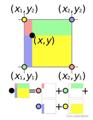
双线性插值的一个计算方法
在CUDA中的双线性插值的计算方式是按下图来处理的,我开始还想着用多个单线性插值计算。实际算法可以比较简单,这个图在很多地方可以看到,图和算法代码结合后发现更好的能去理解算法。

CUDA 实现双线性插值的函数bilinear_interpolate如下:
template <typename scalar_t>

/* scalar_t:  是一个宏,特化的时候会传入具体的类型。(只需要认为是个可以变换的标量类型,调用者给啥类型就是啥类型,从定义来看实际为float类型)
bottom_data:征图是(h*w)的一维数组。(其实就是输入要处理的图像或矩阵值)
height/width:特征图的高宽
xy : 要差值的点的坐标
*/

__device__ scalar_t bilinear_interpolate(const scalar_t *bottom_data,
                                         const int height, const int width,
                                         scalar_t y, scalar_t x) {
  // deal with cases that inverse elements are out of feature map boundary  后面几句是保证取的特征点是在图像范围内。
  if (y < -1.0 || y > height || x < -1.0 || x > width) {
    return 0;
  }

  if (y <= 0) y = 0;
  if (x <= 0) x = 0;

  int y_low = (int)y;
  int x_low = (int)x;
  int y_high;
  int x_high;
  //计算双线性插值的的边界,转换为整形。浮点转整形的误差,需要特殊处理保证y_low ,y_high和x_low,x_high至少有1的差距。否则可能Y或X取同一个Y或X的4个点
  if (y_low >= height - 1) {
    y_high = y_low = height - 1;
    y = (scalar_t)y_low;
  } else {
    y_high = y_low + 1;
  }

  if (x_low >= width - 1) {
    x_high = x_low = width - 1;
    x = (scalar_t)x_low;
  } else {
    x_high = x_low + 1;
  }
  //计算x y点对应4个边的距离关系。
  scalar_t ly = y - y_low;
  scalar_t lx = x - x_low;
  scalar_t hy = 1. - ly;
  scalar_t hx = 1. - lx;
  // do bilinear interpolation
  //获取输入的4个参与计算的点的值
  scalar_t lt = bottom_data[y_low * width + x_low];
  scalar_t rt = bottom_data[y_low * width + x_high];
  scalar_t lb = bottom_data[y_high * width + x_low];
  scalar_t rb = bottom_data[y_high * width + x_high];
  //计算双线性插值的点的值,使用类似面积关系计算(看上面的双线性计算的一个图能更好的理解下面两句话)
  scalar_t w1 = hy * hx, w2 = hy * lx, w3 = ly * hx, w4 = ly * lx;

  scalar_t val = (w1 * lt + w2 * rt + w3 * lb + w4 * rb);

  return val;
}
整个旋转的RIO源码:
template <typename scalar_t>
__global__ void ROIAlignRotatedForward(const int nthreads, const scalar_t *bottom_data,
                                const scalar_t *bottom_rois,
                                const scalar_t spatial_scale,
                                const int sample_num, const int channels,
                                const int height, const int width,
                                const int pooled_height, const int pooled_width,
                                scalar_t *top_data) {
		/*
		nthreads:线程号,可以将计算变成多个线程并行执行
		aligned_height,aligned_width分别表示pooling后的h和pooling后的w,channels表示通道数(pooling前后不变)。每个线程负责一个pooling结果,所以这个数值也是线程总数量
		bottom_data:需要进行roialign的featuremap的首地址,输入处理的内容地址。
		spatial_scale:原图和特诊图之间的比例。原图的height/特征图的height
		height:输入特征图的height
		width:输入特征图的width
		sample_num:每个bin里面采样蓝点的数量为 sample_num*sample_num,一般为2x2=4
		channels:输入特征图的channels(通道数理解为1个输入的特征点使用几个变量表示)
		bottom_rois:存储rois设置首地址,rois设置为(num_rois * 6)一维数组。[[batch_index,x1,y1,x2,y2,θ],...]
		top_data:pooling结果的首地址,最后的结果存储在这里。它的形状是(num_rois * aligned_height * aligned_width * channels)一维数组,每一个都和index对应。
		*/

	//index 对应我OPENCL的相关int globleSize = get_global_size(0),nthreads对应int gid = get_global_id(0);

    CUDA_1D_KERNEL_LOOP(index, nthreads) {
    // (n, c, ph, pw) is an element in the pooled output  因为整体输入是被分成的多个线程即不同的GPU进行分块处理的,所以不同index 的的程序处理的输入范围有区别,通过(n, c, ph, pw)可以知道获取的输入的相关位置。
    //其中N对应了输入设置的第几个
    int pw = index % pooled_width;
    int ph = (index / pooled_width) % pooled_height;
    int c = (index / pooled_width / pooled_height) % channels;
    int n = index / pooled_width / pooled_height / channels;


    const scalar_t* offset_bottom_rois = bottom_rois + n * 6;//由于有6个变量设置,所以一次需要跳6个
    int roi_batch_ind = offset_bottom_rois[0];//当前roi属于当前batch中的偏移(从0开始排序)

    // Do not using rounding; this implementation detail is critical //不要使用四舍五入; 这个实现细节很关键
    //下面是从bottom_rois 获取相关计算参数
    scalar_t roi_center_w = offset_bottom_rois[1] * spatial_scale;//RIO 中心点的X坐标?
    scalar_t roi_center_h = offset_bottom_rois[2] * spatial_scale;//RIO 中心点的Y坐标?
    scalar_t roi_width = offset_bottom_rois[3] * spatial_scale;//RIO区域 的宽
    scalar_t roi_height = offset_bottom_rois[4] * spatial_scale;//RIO区域 的高
    // scalar_t theta = offset_bottom_rois[5] * M_PI / 180.0;
    scalar_t theta = offset_bottom_rois[5];//RIO的旋转角度

    // Force malformed ROIs to be 1x1 限制 ROIs 大小 为1X1 以上
    roi_width = max(roi_width, (scalar_t)1.);//保证roi_width 不小于1
    roi_height = max(roi_height, (scalar_t)1.);//保证roi_height不小于1
    scalar_t bin_size_h = static_cast<scalar_t>(roi_height) / static_cast<scalar_t>(pooled_height);//计算出高度上的压缩比
    scalar_t bin_size_w = static_cast<scalar_t>(roi_width) / static_cast<scalar_t>(pooled_width);//计算出宽度上的压缩比

    const scalar_t* offset_bottom_data = bottom_data + (roi_batch_ind * channels + c) * height * width;//计算第一个点在输入数据中的位置

    // We use roi_bin_grid to sample the grid and mimic integral 、、使用 roi_bin_grid 对网格进行采样并模拟积分,bin是什么看上一篇文章有说明。
   //roi_bin_grid_h roi_bin_grid_w 一般为都为2可以看上篇文章的标准bin,sample_num 为2的图理解
    int roi_bin_grid_h = (sample_num > 0)//设置了sample_num那么使用sample_num 否则使用压缩比值作为bin的高度。
        ? sample_num
        : ceil(roi_height / pooled_height);  // e.g., = 2  //ceil返回大于或者等于指定表达式的最小整数
    int roi_bin_grid_w =
        (sample_num > 0) ? sample_num : ceil(roi_width / pooled_width); //ceil返回大于或者等于指定表达式的最小整数

    // roi_start_h and roi_start_w are computed wrt the center of RoI (x, y).roi_start_h 和 roi_start_w 是根据 RoI 的中心计算的
    // Appropriate translation needs to be applied after.
    scalar_t roi_start_h = -roi_height / 2.0;
    scalar_t roi_start_w = -roi_width / 2.0;
    scalar_t cosscalar_theta = cos(theta);
    scalar_t sinscalar_theta = sin(theta);

    // We do average (integral) pooling inside a bin  在 bin 内进行平均(积分)池化
    const scalar_t count = roi_bin_grid_h * roi_bin_grid_w;  // e.g. = 4 //每个bin分成了4个小块,看看上篇文章的标准bin,sample_num 为2的图理解

    scalar_t output_val = 0.;
    // y方向处理所有采样点
    for (int iy = 0; iy < roi_bin_grid_h; iy++) {  // e.g., iy = 0, 1
       //yy xx 未旋转前采样点与中心点的位置关系
        const scalar_t yy = roi_start_h + ph * bin_size_h +
            static_cast<scalar_t>(iy + .5f) * bin_size_h /
                static_cast<scalar_t>(roi_bin_grid_h);  // e.g., 0.5, 1.5
        // x方向处理所有采样点
        for (int ix = 0; ix < roi_bin_grid_w; ix++) {
        const scalar_t xx = roi_start_w + pw * bin_size_w +
            static_cast<scalar_t>(ix + .5f) * bin_size_w /
                static_cast<scalar_t>(roi_bin_grid_w);

        // Rotate by theta around the center and translate
        // scalar_t x = xx * cosscalar_theta + yy * sinscalar_theta + roi_center_w;
        // scalar_t y = yy * cosscalar_theta - xx * sinscalar_theta + roi_center_h;
        //y x 是bin分区域后的每个采样点的位置,实际理解为上篇文章的,旋转后BIN 中的小黑点的X,Y轴的位置
        scalar_t x = xx * cosscalar_theta - yy * sinscalar_theta + roi_center_w;
        scalar_t y = xx * sinscalar_theta + yy * cosscalar_theta + roi_center_h;

        scalar_t val = bilinear_interpolate<scalar_t>(//计算点的双线性插值后的结果。
            offset_bottom_data, height, width, y, x);
        output_val += val;
        }
    }
    output_val /= count;//取采样点的均值

    top_data[index] = output_val;
    }
}