FPGA实现Sobel算子边缘提取(简单记录)
写在前面的
趁着最近这段时间课多,没有给我用来复习的集中时间,把之前没做完的图像Sobel算子边缘提取给完成了。
开发工具
1、
开发平台
:Vivado 2018.3
2、
FPGA
:Zynq7010
Sobel算子使用的简单介绍
Sobel算子是两个3*3的矩阵,分别是一个x方向的矩阵和一个y方向的矩阵。使用两个矩阵与原图像灰度图做卷积运算,得到x方向G(x)和y方向G(y),再将两者平方的和相加开根号得到G,G为该点的梯度值,该梯度值大于一定阈值,则认为该点为图像的边缘点。
以下为Sobel算子的使用,以图像的方式:
1、x方向和y方向矩阵与原图像灰度图做卷积

2、计算梯度

3、计算梯度方向

4、x方向和y方向矩阵与原图像灰度图卷积具体计算

5、一般为了提高效率不做开方处理,取绝对值

FPGA实现过程
一、顶层模块

一共有8个module,分为四个大类:HDMI输出部分、图像存储部分、图像处理部分以及时钟分频部分。其中本文章着重分享图像处理部分。(臃肿的代码就不贴出来给各位看了,其中还有一部分别的module的例化懒得删。。)
二、灰度转化
先贴代码(了解给为老铁的心思)
`timescale 1ns / 1ps

module gray(
    input        pixelclk,
    input        rst_n,
    input [23:0] din,
    input        i_video_hs,
    input        i_video_vs,
    input        i_video_de,
    input        area,

    output[23:0] dout
    );

    localparam one_third = 85; // 1/3 = 0.3333333 * 2^8;

    wire [15:0] r,g,b;
    reg  [23:0] gray;
    reg         video_hs;
    reg         video_vs;
    reg         video_de;
    wire [23:0] data;

    always@(posedge pixelclk)
    begin
        video_hs <= i_video_hs;
        video_vs <= i_video_vs;
        video_de <= i_video_de;
    end

    assign r = {din[23:16],8'd0};
    assign g = {din[15:8],8'd0};
    assign b = {din[7:0],8'd0};
    assign o_video_hs = video_hs;
    assign o_video_vs = video_vs;
    assign o_video_de = video_de;

    always@(posedge pixelclk or negedge rst_n)
    begin
        if(!rst_n)
            gray <= 0;
        else if(area)
        begin
            gray <= (r+g+b)*one_third;
        end
        else
        begin
            gray <= 0;
        end
    end

    assign data = {gray[23:16],gray[23:16],gray[23:16]};
    assign dout = data;


endmodule
-
主要的部分就最后那一个always块,将24位的RGB888的数据拆分为三个8位的数据(分别对应R、G、B三个通道),然后三个通道的数据相加除与1/3,就得到了起灰度值。这里有一个点很重要,值得我学习。在FPGA内部,分数以及小数是不能产生的,于是小数(和分数)都要做一定的处理才行。以前做图像旋转时,我是将正余弦函数值扩大10000倍然后再进行计算,这种将小数放大的方法我觉得很不实用,于是就有了上面代码的方法,将浮点数转化为定点数。于是有了这条注释:
1/3
= 0.3333333 * 2^8
三、图像行缓存
FPGA实现图像3*3矩阵
(这个自己真想不到怎么写,没办法自己太菜了。。这个博主的代码挺好,用起来很香,嘿嘿)
`timescale 1ns / 1ps

module linebuffer_3x3(
    input           pixel_clk,
    input           rst_n,
    input [7:0]     din,
    input           i_video_hs,
    input           i_video_vs,
    input           i_video_de,
    input           area,
    input [16:0]    address,

    output          o_video_hs,
    output          o_video_vs,
    output          o_video_de,

	output 	[7:0]	matrix_p11,
	output 	[7:0]	matrix_p12,
	output 	[7:0]	matrix_p13,
	output 	[7:0]	matrix_p21,
	output 	[7:0]	matrix_p22,
	output 	[7:0]	matrix_p23,
	output 	[7:0]	matrix_p31,
	output 	[7:0]	matrix_p32,
	output 	[7:0]	matrix_p33
    );

    wire 	[7:0] 	row1_data;//frame data of the 1th row
    wire 	[7:0]	row2_data;//frame data of the 2th row
    reg 	[7:0] 	row3_data;//frame data of the 3th row

    reg 	[7:0]	matrix_p11_reg;
    reg		[7:0]	matrix_p12_reg;
    reg		[7:0]	matrix_p13_reg;
    reg		[7:0]	matrix_p21_reg;
    reg		[7:0]	matrix_p22_reg;
    reg		[7:0]	matrix_p23_reg;
    reg		[7:0]	matrix_p31_reg;
    reg		[7:0]	matrix_p32_reg;
    reg		[7:0]	matrix_p33_reg;

    reg             en;

    always @(posedge pixel_clk or negedge rst_n)begin
	if(!rst_n)
		row3_data <= 8'b0;
	else begin
		if(area)
			row3_data <= din;
		else
			row3_data <= row3_data;
		end
    end

    line_buffer u_shift_ram_3X3_12bit_1(
      .D(row3_data),      // input wire [7 : 0] D
      .CLK(pixel_clk),  // input wire CLK
      .CE(area),    // input wire CE
      .Q(row2_data)      // output wire [7 : 0] Q
    );

    line_buffer u_shift_ram_3X3_12bit_2(
      .D(row2_data),      // input wire [7 : 0] D
      .CLK(pixel_clk),  // input wire CLK
      .CE(area),    // input wire CE
      .Q(row1_data)      // output wire [7 : 0] Q
    );


always @(posedge pixel_clk or negedge rst_n)begin
    if(!rst_n)begin
        {matrix_p11_reg, matrix_p12_reg, matrix_p13_reg} <= 24'h0;
        {matrix_p21_reg, matrix_p22_reg, matrix_p23_reg} <= 24'h0;
        {matrix_p31_reg, matrix_p32_reg, matrix_p33_reg} <= 24'h0;
    end
    else if(area)
    begin
            {matrix_p11_reg, matrix_p12_reg, matrix_p13_reg} <= {matrix_p12_reg, matrix_p13_reg, row1_data};//1th shift input
            {matrix_p21_reg, matrix_p22_reg, matrix_p23_reg} <= {matrix_p22_reg, matrix_p23_reg, row2_data};//2th shift input
            {matrix_p31_reg, matrix_p32_reg, matrix_p33_reg} <= {matrix_p32_reg, matrix_p33_reg, row3_data};//3th shift input
    end
    else
    begin
        {matrix_p11_reg, matrix_p12_reg, matrix_p13_reg} <= {matrix_p11_reg, matrix_p12_reg, matrix_p13_reg};
        {matrix_p21_reg, matrix_p22_reg, matrix_p23_reg} <= {matrix_p21_reg, matrix_p22_reg, matrix_p23_reg};
        {matrix_p31_reg, matrix_p32_reg, matrix_p33_reg} <= {matrix_p31_reg, matrix_p32_reg, matrix_p33_reg};
    end
end

///这里做的是将数据对齐
always@(*)
begin
    if(address >= 647 && address <76800)
        en <= 1;
    else
        en <= 0;
end

    assign {matrix_p11, matrix_p12, matrix_p13} =  en ? {matrix_p11_reg, matrix_p12_reg, matrix_p13_reg} : {7'd0,7'd0,7'd0};
    assign {matrix_p21, matrix_p22, matrix_p23} =  en ? {matrix_p21_reg, matrix_p22_reg, matrix_p23_reg} : {7'd0,7'd0,7'd0};
    assign {matrix_p31, matrix_p32, matrix_p33} =  en ? {matrix_p31_reg, matrix_p32_reg, matrix_p33_reg} : {7'd0,7'd0,7'd0};

endmodule
IP配置


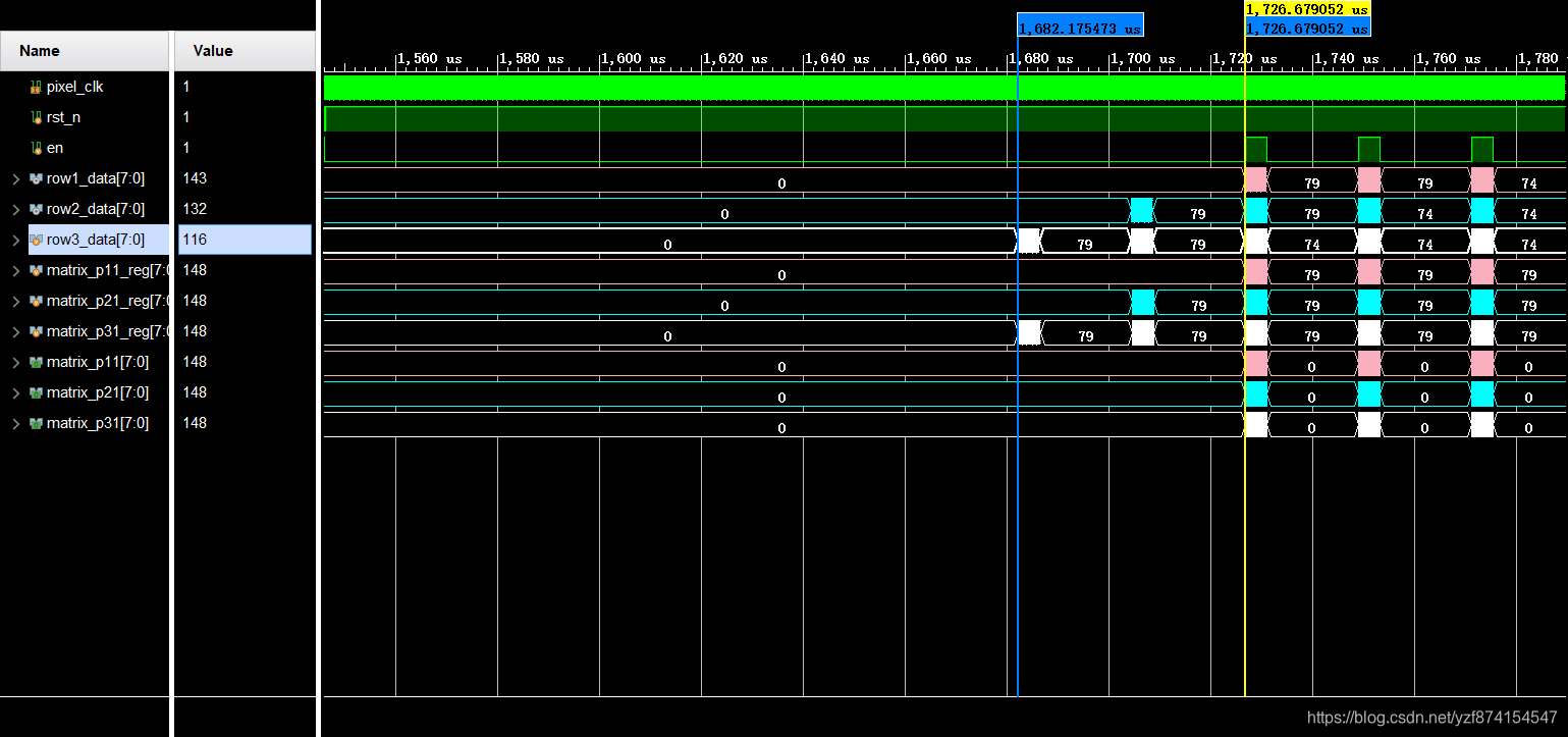
这部分一定要放仿真,不然讲不清。

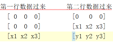
实现3*3矩阵是一行一行来做的,所以如果不做数据对齐,现象就是上面图中matrix_p11_reg、matrix_p21_reg、matrix_p31_reg,每组相差一行的距离。我通过计算它什么时候结束前两行的缓存,依次作为标准将matrix_p11_reg、matrix_p21_reg、matrix_p31_reg三组数据前两行部分的给去掉,达到对其的效果。
(为什么要对齐?前两行的数据过来的情况如下图。)

四、Sobel实现
`timescale 1ns / 1ps

module sobe_convolution(
    input                  pixel_clk,
    input                  rst_n,
    input                  i_video_hs,
    input                  i_video_vs,
    input                  i_video_de,
    input                  area,

    input [7:0]	           matrix_p11,
	input [7:0]	           matrix_p12,
	input [7:0]	           matrix_p13,
	input [7:0]	           matrix_p21,
	input [7:0]	           matrix_p22,
	input [7:0]	           matrix_p23,
	input [7:0]	           matrix_p31,
	input [7:0]	           matrix_p32,
	input [7:0]	           matrix_p33,

    output reg [7:0]       dout
    );

    localparam Gx_h_1_v_1 = 8'hff;
    localparam Gx_h_1_v_2 = 8'h00;
    localparam Gx_h_1_v_3 = 8'h01;

    localparam Gx_h_2_v_1 = 8'hfe;
    localparam Gx_h_2_v_2 = 8'h00;
    localparam Gx_h_2_v_3 = 8'h02;

    localparam Gx_h_3_v_1 = 8'hff;
    localparam Gx_h_3_v_2 = 8'h00;
    localparam Gx_h_3_v_3 = 8'h01;

    localparam Gy_h_1_v_1 = 8'h01;
    localparam Gy_h_1_v_2 = 8'h02;
    localparam Gy_h_1_v_3 = 8'h01;

    localparam Gy_h_2_v_1 = 8'h00;
    localparam Gy_h_2_v_2 = 8'h00;
    localparam Gy_h_2_v_3 = 8'h00;

    localparam Gy_h_3_v_1 = 8'hff;
    localparam Gy_h_3_v_2 = 8'hfe;
    localparam Gy_h_3_v_3 = 8'hff;

    wire signed [15:0] Gx_p11;
    wire signed [15:0] Gx_p12;
    wire signed [15:0] Gx_p13;

    wire signed [15:0] Gx_p21;
    wire signed [15:0] Gx_p22;
    wire signed [15:0] Gx_p23;

    wire signed [15:0] Gx_p31;
    wire signed [15:0] Gx_p32;
    wire signed [15:0] Gx_p33;


    wire signed [15:0] Gy_p11;
    wire signed [15:0] Gy_p12;
    wire signed [15:0] Gy_p13;

    wire signed [15:0] Gy_p21;
    wire signed [15:0] Gy_p22;
    wire signed [15:0] Gy_p23;

    wire signed [15:0] Gy_p31;
    wire signed [15:0] Gy_p32;
    wire signed [15:0] Gy_p33;

    wire signed [15:0] Gx;
    wire signed [15:0] Gy;
    wire [23:0] G;
    wire [15:0] data;

    mult_gen_0 mul_px11(
      .CLK(pixel_clk),  // input wire CLK
      .A(matrix_p11),      // input wire [7 : 0] A
      .B(Gx_h_1_v_1),      // input wire [7 : 0] B
      .CE(area),    // input wire CE
      .P(Gx_p11)      // output wire [15 : 0] P
    );

    mult_gen_0 mul_px12(
      .CLK(pixel_clk),  // input wire CLK
      .A(matrix_p12),      // input wire [7 : 0] A
      .B(Gx_h_1_v_2),      // input wire [7 : 0] B
      .CE(area),    // input wire CE
      .P(Gx_p12)      // output wire [15 : 0] P
    );

    mult_gen_0 mul_px13(
      .CLK(pixel_clk),  // input wire CLK
      .A(matrix_p13),      // input wire [7 : 0] A
      .B(Gx_h_1_v_3),      // input wire [7 : 0] B
      .CE(area),    // input wire CE
      .P(Gx_p13)      // output wire [15 : 0] P
    );

    mult_gen_0 mul_px21(
      .CLK(pixel_clk),  // input wire CLK
      .A(matrix_p21),      // input wire [7 : 0] A
      .B(Gx_h_2_v_1),      // input wire [7 : 0] B
      .CE(area),    // input wire CE
      .P(Gx_p21)      // output wire [15 : 0] P
    );

    mult_gen_0 mul_px22(
      .CLK(pixel_clk),  // input wire CLK
      .A(matrix_p22),      // input wire [7 : 0] A
      .B(Gx_h_2_v_2),      // input wire [7 : 0] B
      .CE(area),    // input wire CE
      .P(Gx_p22)      // output wire [15 : 0] P
    );

    mult_gen_0 mul_px23(
      .CLK(pixel_clk),  // input wire CLK
      .A(matrix_p23),      // input wire [7 : 0] A
      .B(Gx_h_2_v_3),      // input wire [7 : 0] B
      .CE(area),    // input wire CE
      .P(Gx_p23)      // output wire [15 : 0] P
    );

    mult_gen_0 mul_px31(
      .CLK(pixel_clk),  // input wire CLK
      .A(matrix_p31),      // input wire [7 : 0] A
      .B(Gx_h_3_v_1),      // input wire [7 : 0] B
      .CE(area),    // input wire CE
      .P(Gx_p31)      // output wire [15 : 0] P
    );

    mult_gen_0 mul_px32(
      .CLK(pixel_clk),  // input wire CLK
      .A(matrix_p32),      // input wire [7 : 0] A
      .B(Gx_h_3_v_2),      // input wire [7 : 0] B
      .CE(area),    // input wire CE
      .P(Gx_p32)      // output wire [15 : 0] P
    );

    mult_gen_0 mul_px33(
      .CLK(pixel_clk),  // input wire CLK
      .A(matrix_p33),      // input wire [7 : 0] A
      .B(Gx_h_3_v_3),      // input wire [7 : 0] B
      .CE(area),    // input wire CE
      .P(Gx_p33)      // output wire [15 : 0] P
    );

    mult_gen_0 mul_py11(
      .CLK(pixel_clk),  // input wire CLK
      .A(matrix_p11),      // input wire [7 : 0] A
      .B(Gy_h_1_v_1),      // input wire [7 : 0] B
      .CE(area),    // input wire CE
      .P(Gy_p11)      // output wire [15 : 0] P
    );

    mult_gen_0 mul_py12(
      .CLK(pixel_clk),  // input wire CLK
      .A(matrix_p12),      // input wire [7 : 0] A
      .B(Gy_h_1_v_2),      // input wire [7 : 0] B
      .CE(area),    // input wire CE
      .P(Gy_p12)      // output wire [15 : 0] P
    );

    mult_gen_0 mul_py13(
      .CLK(pixel_clk),  // input wire CLK
      .A(matrix_p13),      // input wire [7 : 0] A
      .B(Gy_h_1_v_3),      // input wire [7 : 0] B
      .CE(area),    // input wire CE
      .P(Gy_p13)      // output wire [15 : 0] P
    );

    mult_gen_0 mul_py21(
      .CLK(pixel_clk),  // input wire CLK
      .A(matrix_p21),      // input wire [7 : 0] A
      .B(Gy_h_2_v_1),      // input wire [7 : 0] B
      .CE(area),    // input wire CE
      .P(Gy_p21)      // output wire [15 : 0] P
    );

    mult_gen_0 mul_py22(
      .CLK(pixel_clk),  // input wire CLK
      .A(matrix_p22),      // input wire [7 : 0] A
      .B(Gy_h_2_v_2),      // input wire [7 : 0] B
      .CE(area),    // input wire CE
      .P(Gy_p22)      // output wire [15 : 0] P
    );

    mult_gen_0 mul_py23(
      .CLK(pixel_clk),  // input wire CLK
      .A(matrix_p23),      // input wire [7 : 0] A
      .B(Gy_h_2_v_3),      // input wire [7 : 0] B
      .CE(area),    // input wire CE
      .P(Gy_p23)      // output wire [15 : 0] P
    );

    mult_gen_0 mul_py31(
      .CLK(pixel_clk),  // input wire CLK
      .A(matrix_p31),      // input wire [7 : 0] A
      .B(Gy_h_3_v_1),      // input wire [7 : 0] B
      .CE(area),    // input wire CE
      .P(Gy_p31)      // output wire [15 : 0] P
    );

    mult_gen_0 mul_py32(
      .CLK(pixel_clk),  // input wire CLK
      .A(matrix_p32),      // input wire [7 : 0] A
      .B(Gy_h_3_v_2),      // input wire [7 : 0] B
      .CE(area),    // input wire CE
      .P(Gy_p32)      // output wire [15 : 0] P
    );

    mult_gen_0 mul_py33(
      .CLK(pixel_clk),  // input wire CLK
      .A(matrix_p33),      // input wire [7 : 0] A
      .B(Gy_h_3_v_3),      // input wire [7 : 0] B
      .CE(area),    // input wire CE
      .P(Gy_p33)      // output wire [15 : 0] P
    );


    assign Gx = Gx_p11 + Gx_p12 + + Gx_p13 + + Gx_p21 + + Gx_p22 + + Gx_p23 + + Gx_p31 + Gx_p32 + Gx_p33;
    assign Gy = Gy_p11 + Gy_p12 + + Gy_p13 + + Gy_p21 + + Gy_p22 + + Gy_p23 + + Gy_p31 + Gy_p32 + Gy_p33;
    assign G  = Gx * Gx + Gy * Gy;

    wire m_axis_dout_tvalid;

    cordic_0 square_root (
      .aclk(pixel_clk),                                        // input wire aclk
      .s_axis_cartesian_tvalid(1),  // input wire s_axis_cartesian_tvalid
      .s_axis_cartesian_tdata(G),    // input wire [23 : 0] s_axis_cartesian_tdata
      .m_axis_dout_tvalid(m_axis_dout_tvalid),            // output wire m_axis_dout_tvalid
      .m_axis_dout_tdata(data)              // output wire [15 : 0] m_axis_dout_tdata
    );

    always@(posedge pixel_clk or negedge rst_n)
    begin
        if(!rst_n)
           dout <= 0;
        else if(area)
            dout <= (data > 100) ? 0 :255;
        else
            dout <= 255;
    end

endmodule
这个地方就没什么重要的,就是做加和乘的运算,一开始没用调IP算的时候出问题,然后没分析为什么有问题,反正只知道用IP没问题。这里调用了CORDIC这个IP,做开方的处理。配置如下,能看的懂选项大概意思就能配,实在不行的自己动手搜索吧。

五、最后结果

下面这个图是因为没做对齐。14个时钟的延迟:2个ROM输出的延迟、1个灰度的延迟、4个矩阵缓存的延迟、7个Sobel处理的延迟。
assign area_x_processing = (pixel_xpos >= pixel_xpos_start + 14)&&(pixel_xpos < pixel_xpos_start + 14 + 320);
assign area_y_processing = (pixel_ypos >= pixel_ypos_start + 2)&&(pixel_ypos < pixel_ypos_start + 2 + 240);
assign area_processing = area_x_processing && area_y_processing;
(应为我时候一个时钟给一个地址,所以我在地址变化后的14个像素后再显示)

总结
个人觉得就3*3矩阵产生那部分和最后那14个时钟延迟的分析比较麻烦意外,其他都挺好做的(除HDMI输出驱动以外)。没事自己就做一点这些不是很麻烦的处理,打发一下备战考研时的疲倦,感觉挺舒服的。推荐一下“FPGA开源工作室”这个公众,还是挺靠谱的,有些时候。