一、modelsim工程仿真流程
代码:
module fulladd(sum,c_out,a,b,c_in);
output sum,c_out;
input a,b,c_in;
wire s1,c1,c2;
xor (s1,a,b);
and (c1,a,b);
xor (sum,s1,c_in);
and (c2,s1,c_in);
or (c_out,c2,c1);
endmodule
庆幸 13:19:36
module test;
wire sum, c_out;
reg a,b,c_in;
fulladd fadd(sun,c_out,a,b,c_in) ;
/*
initial
begin
#15 force fadd.sum=a&b&c_in;
#20 release fadd.sun;
#10 $stop;
end
*/
initial
begin
a=0;b=0;c_in=0;
#10 a=0;b=0;c_in=1;
#10 a=0;b=1;c_in=0;
#10 a=0;b=1;c_in=1;
#10 a=1;b=0;c_in=0;
#10 a=1;b=0;c_in=1;
#10 a=1;b=1;c_in=0;
#10 a=1;b=1;c_in=1;
#10 $stop;
end
endmodule
1.添加现有代码的文件或者创建文件然后打入代码。

2.进行编译,看是否有错误。

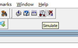
3.点击simulate。

4.点击work,然后选择好我们的测试文件,然后点击ok。

5.点击上图ok后,就会生成sim界面如下图。

6.选中测试文件,右键点击选择add wave。

7.再点击run all,就会出现wave图,如下

8.本次实验就是这样,谢谢观看。

二、主从D触发器的门级建模
代码:
module tb_23;
reg d;
reg clk;
wire q, qbar;
initial clk=0;
always #5 clk=~clk;
initial
begin
d=0 ;
#7 d=1;
#4 d=0;
#9 d=1;
#11 d=0;
#20 $stop;
end
MSDFF ms_dff(q,qbar,d,clk);
endmodule
module MSDFF(Q,Qbar,D,C);
output Q,Qbar;
input D , C;
not
not1 ( NotD ,D) ,
not2 ( Notc , C) ,
not3 ( NotY , Y);
nand
nand1 ( D1 , D ,C ) ,
nand2 ( D2 , c , NotD) ,
nand3 ( y , D1 , Ybar ) ,
nand4 ( ybar , Y , D2) ,
nand5 ( y1 , r , NotC) ,
nand6 ( Y2 , NotY , NotC) ,
nana7 (Q, Qbar, Y1) ,
nand8 (Qbar , Y2 , Q) ;
endmodule
1.本次实验与上面第一个实验步骤相仿,大家可以参考上面的过程。
最终的wave图如下:
