目录
一、整体说明
使用cubemx生成hal库的adc代码,这个已经有很多博文有了,这里不再赘述。我使用的是STM32F4,GCC编译环境,测两路电压和一路内部温度。使用了连续模式,比较容易实现,但由于我这个工程不需要太快的速度和数据量,
所以需要软件触发,不再使用连续模式,
主要是改成这样遇到一些问题,记录下来供参考。
二、部分知识点预览
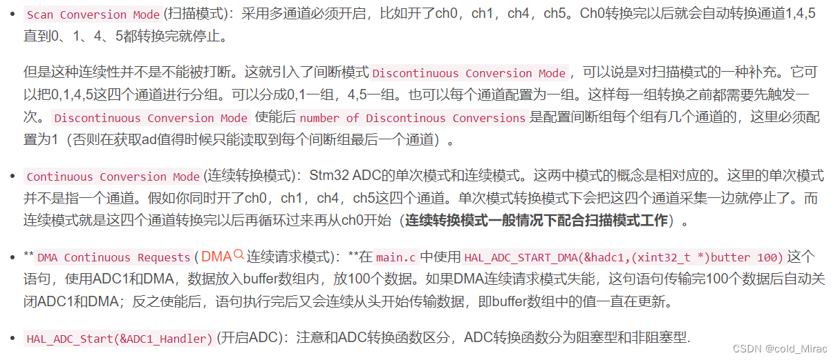
1、连续模式和间断模式参数
参考博文
stm32ADC DMA 多通道采集(包含定时器)(HAL库)_yanwu_nuc的博客-CSDN博客_stm32adc多通道采集

三、代码部分
/**
******************************************************************************
* File Name : ADC.c
* Description : This file provides code for the configuration
* of the ADC instances.
******************************************************************************
* @attention
*
* <h2><center>© Copyright (c) 2022 STMicroelectronics.
* All rights reserved.</center></h2>
*
* This software component is licensed by ST under BSD 3-Clause license,
* the "License"; You may not use this file except in compliance with the
* License. You may obtain a copy of the License at:
* opensource.org/licenses/BSD-3-Clause
*
******************************************************************************
*/
/* Includes ------------------------------------------------------------------*/
#include "adc.h"
/* USER CODE BEGIN 0 */
unsigned short u16ADCDMAVal[MAX_ADC_CH_NUM];
/* USER CODE END 0 */
ADC_HandleTypeDef hadc1;
DMA_HandleTypeDef hdma_adc1;
/* ADC1 init function */
void MX_ADC1_Init(void)
{
ADC_ChannelConfTypeDef sConfig = {0};
/** Configure the global features of the ADC (Clock, Resolution, Data Alignment and number of conversion)
*/
hadc1.Instance = ADC1;
hadc1.Init.ClockPrescaler = ADC_CLOCK_SYNC_PCLK_DIV8;
hadc1.Init.Resolution = ADC_RESOLUTION_12B;
hadc1.Init.ScanConvMode = ENABLE;
hadc1.Init.ContinuousConvMode = DISABLE;
hadc1.Init.DiscontinuousConvMode = DISABLE;//DISABLE ENABLE
hadc1.Init.ExternalTrigConvEdge = ADC_EXTERNALTRIGCONVEDGE_NONE;
hadc1.Init.ExternalTrigConv = ADC_SOFTWARE_START;
hadc1.Init.DataAlign = ADC_DATAALIGN_RIGHT;
hadc1.Init.NbrOfConversion = 3;
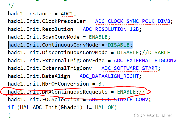
hadc1.Init.DMAContinuousRequests = ENABLE;//
hadc1.Init.EOCSelection = ADC_EOC_SINGLE_CONV;
if (HAL_ADC_Init(&hadc1) != HAL_OK)
{
Error_Handler();
}
/** Configure for the selected ADC regular channel its corresponding rank in the sequencer and its sample time.
*/
sConfig.Channel = ADC_CHANNEL_10;
sConfig.Rank = 1;
sConfig.SamplingTime = ADC_SAMPLETIME_480CYCLES;
if (HAL_ADC_ConfigChannel(&hadc1, &sConfig) != HAL_OK)
{
Error_Handler();
}
/** Configure for the selected ADC regular channel its corresponding rank in the sequencer and its sample time.
*/
sConfig.Channel = ADC_CHANNEL_5;
sConfig.Rank = 2;
if (HAL_ADC_ConfigChannel(&hadc1, &sConfig) != HAL_OK)
{
Error_Handler();
}
/** Configure for the selected ADC regular channel its corresponding rank in the sequencer and its sample time.
*/
sConfig.Channel = ADC_CHANNEL_TEMPSENSOR;
sConfig.Rank = 3;
if (HAL_ADC_ConfigChannel(&hadc1, &sConfig) != HAL_OK)
{
Error_Handler();
}
}
void HAL_ADC_MspInit(ADC_HandleTypeDef* adcHandle)
{
GPIO_InitTypeDef GPIO_InitStruct = {0};
if(adcHandle->Instance==ADC1)
{
/* USER CODE BEGIN ADC1_MspInit 0 */
/* USER CODE END ADC1_MspInit 0 */
/* ADC1 clock enable */
__HAL_RCC_ADC1_CLK_ENABLE();
__HAL_RCC_GPIOC_CLK_ENABLE();
__HAL_RCC_GPIOA_CLK_ENABLE();
/**ADC1 GPIO Configuration
PC0 ------> ADC1_IN10
PA5 ------> ADC1_IN5
*/
GPIO_InitStruct.Pin = ADC_12V_Pin;
GPIO_InitStruct.Mode = GPIO_MODE_ANALOG;
GPIO_InitStruct.Pull = GPIO_NOPULL;
HAL_GPIO_Init(ADC_12V_GPIO_Port, &GPIO_InitStruct);
GPIO_InitStruct.Pin = GPIO_PIN_5;
GPIO_InitStruct.Mode = GPIO_MODE_ANALOG;
GPIO_InitStruct.Pull = GPIO_NOPULL;
HAL_GPIO_Init(GPIOA, &GPIO_InitStruct);
/* ADC1 DMA Init */
/* ADC1 Init */
hdma_adc1.Instance = DMA2_Stream0;
hdma_adc1.Init.Channel = DMA_CHANNEL_0;
hdma_adc1.Init.Direction = DMA_PERIPH_TO_MEMORY;
hdma_adc1.Init.PeriphInc = DMA_PINC_DISABLE;
hdma_adc1.Init.MemInc = DMA_MINC_ENABLE;
hdma_adc1.Init.PeriphDataAlignment = DMA_PDATAALIGN_HALFWORD;
hdma_adc1.Init.MemDataAlignment = DMA_MDATAALIGN_HALFWORD;
hdma_adc1.Init.Mode = DMA_CIRCULAR;
hdma_adc1.Init.Priority = DMA_PRIORITY_HIGH;
hdma_adc1.Init.FIFOMode = DMA_FIFOMODE_DISABLE;
if (HAL_DMA_Init(&hdma_adc1) != HAL_OK)
{
Error_Handler();
}
__HAL_LINKDMA(adcHandle,DMA_Handle,hdma_adc1);
/* ADC1 interrupt Init */
HAL_NVIC_SetPriority(ADC_IRQn, 0, 0);
HAL_NVIC_EnableIRQ(ADC_IRQn);
/* USER CODE BEGIN ADC1_MspInit 1 */
/* USER CODE END ADC1_MspInit 1 */
}
}
void HAL_ADC_MspDeInit(ADC_HandleTypeDef* adcHandle)
{
if(adcHandle->Instance==ADC1)
{
/* USER CODE BEGIN ADC1_MspDeInit 0 */
/* USER CODE END ADC1_MspDeInit 0 */
/* Peripheral clock disable */
__HAL_RCC_ADC1_CLK_DISABLE();
/**ADC1 GPIO Configuration
PC0 ------> ADC1_IN10
PA5 ------> ADC1_IN5
*/
HAL_GPIO_DeInit(ADC_12V_GPIO_Port, ADC_12V_Pin);
HAL_GPIO_DeInit(GPIOA, GPIO_PIN_5);
/* ADC1 DMA DeInit */
HAL_DMA_DeInit(adcHandle->DMA_Handle);
/* ADC1 interrupt Deinit */
HAL_NVIC_DisableIRQ(ADC_IRQn);
/* USER CODE BEGIN ADC1_MspDeInit 1 */
/* USER CODE END ADC1_MspDeInit 1 */
}
}
/* USER CODE BEGIN 1 */
void adc_deinit(void)
{
HAL_ADC_MspDeInit(&hadc1);
}
/* USER CODE END 1 */
/************************ (C) COPYRIGHT STMicroelectronics *****END OF FILE****/
main函数中只需要初始化MX_DMA_Init MX_ADC1_Init
然后再软件调用 HAL_ADC_Start_DMA(&hadc1, test_adcbuf, 30) 或者HAL_ADC_Start(&hadc1)即可。test_adcbuf为uint16_t数据类型。如果是连续模式只需要设置hadc1.Init.ContinuousConvMode = ENABLE;
HAL_ADC_Start_DMA(&hadc1, test_adcbuf, 30)调用一次即可。
四、遇到的问题及现象
(1)仿真进入错误

DMAContinuousRequests若改为disable,则会进入仿真错误Infinite_loop死机,如下图所示:

(2)非连续模式软件触发时adcbuf里面的数据不对
hadc1.Init.ContinuousConvMode = DISABLE;
hadc1.Init.DiscontinuousConvMode = D ENABLE
如上这样配置则会导致ADCbuf里面的数据不对,需要将不间断模式disable

(3)HAL库的ADC DMA相关中断的嵌套实现
HAL库自己嵌套了,我们只需要编写这两个回调函数就行了
HAL_ADC_ConvHalfCpltCallback
HAL_ADC_ConvCpltCallback

五、结论
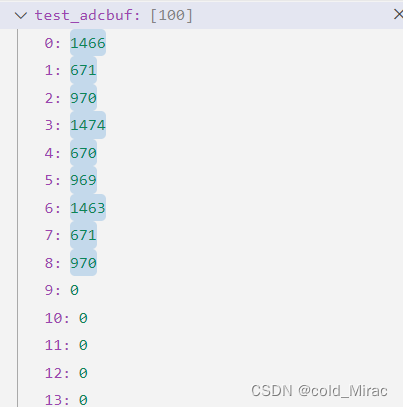
(1)我将HAL_ADC_Start_DMA(&hadc1, test_adcbuf, 9) 设置为1次dma传输完成为9个数据,读到的数据如下,通道1约为1.5V电压。
(2)DMA+ADC重点应该还是几个配置参数的理解和设置要对。
说明:这个start函数只要第一次设置为9,再设置为其他值就无效了

