文章目录
一、动态显示电路
(1)实验目的
1、掌握二进制译码器、二-十进制译码器和显示译码器的逻辑功能及各种应用。
2、熟悉十进制数字显示电路的构成方法。
3、了解动态扫描显示方式的电路工作原理及优点。
(2)实验原理或设计过程
1.译码器及其应用:译码器一般都是具有 n 个输入和 m 个输出的组合逻辑电路,常用的译码器是有成品的,只要根据需要选用合适的型号就行了,无需自己进行设计。译码器按用途大致可以分为两类:二进制译码器和二-十进制译码器。
2.显示译码器和数码管的应用:在许多数字系统里,希望把数字信息加工处理的中间结果或最终结果通过数字显示器件显示出来,以便于了解和判断系统的运行情况,这时就要用到数字显示译码器。
四位动态显示电路,内容为学号的后四位,2418
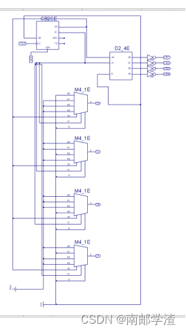
动态显示包括四个方面:控制部分、数据选择部分、译码驱动和显示部分。4 位数码管共用一个 7448BCD 译码器。半导体数码管既有共阴结构又有共阳结构, 我们这里采用共阴数码管。用两片 74LS74N 输出信号 Q1、Q2 作为一片 74139 和两片 74153 的地址线。而 74139 的输出信号 Y0、Y1、Y2、Y3 则分别作为 4 位数码管的位线。4 位数码管的 4 根数据线,由 4 个四选一多路选择器输出。最后根据自己想要得出的动态显示结果,对 74153 相应的端口进行接线。
(3)实验电路图

(4)实验数据分析和实验结果
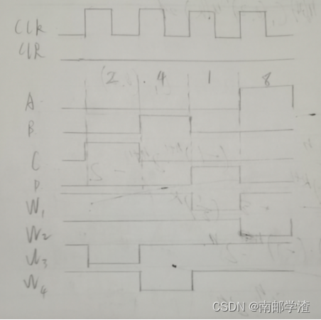
四位动态显示电路,内容为学号的后四位,2418.

(5)RTL代码实现(加分项)
注:本代码给出的是六段数码管从0记到999999个数字的的RTL代码,有基础或者想要深入学习的同学可以尝试更改为适合南邮实验平台的四段数码管输入,此代码相较学习的知识超纲了,可以跳过。
hex.v代码
module hex
#(
	parameter CNT_MAX=16'd49_999,//4_999_999
	parameter DATA_MAX=20'd999_999
)
(

	input wire clk,
	input wire rst_n,

	output reg [19:0]data,
	output wire [5:0]point,
	output reg seg_en,
	output wire sign

);

	reg [15:0]cnt_100ms;
	reg cnt_flag;

	assign point=6'b000_000;
	assign sign=1'b0;

	always @(posedge clk or negedge rst_n)
	if(!rst_n)
		cnt_100ms<=1'b0;
	else if(cnt_100ms==CNT_MAX)
		cnt_100ms<=1'b0;
	else
		cnt_100ms<=cnt_100ms+1'b1;

	always @(posedge clk or negedge rst_n)
	if(!rst_n)
		cnt_flag<=1'b0;
	else if(cnt_100ms==CNT_MAX-1)
		cnt_flag<=1'b1;
	else
		cnt_flag<=1'b0;

	always@(posedge clk or negedge rst_n)
	if(!rst_n)
		data<=1'b0;
	else if(data==DATA_MAX && cnt_100ms==CNT_MAX)
		data<=1'b0;
	else if(cnt_flag)
		data<=data+1'b1;
	else
		data<=data;

	always @(posedge clk or negedge rst_n)
	if(!rst_n)
		seg_en<=1'b0;
	else
		seg_en<=1'b1;

endmodule
bcd_8421.v代码
module bcd_8421(

	input wire clk,
	input wire rst_n,
	input wire [19:0]data,

	output reg [3:0]unit,
	output reg [3:0]ten,
	output reg [3:0]hun,
	output reg [3:0]tho,
	output reg [3:0]t_tho,
	output reg [3:0]h_hun

);

	reg [4:0]cnt_shift;
	reg [43:0]data_shift;
	reg shift_flag;

	always @(posedge clk or negedge rst_n)
	if(!rst_n)
		cnt_shift<=1'b0;
	else if(cnt_shift==5'd21 && shift_flag)
		cnt_shift<=1'b0;
	else if(shift_flag)
		cnt_shift<=cnt_shift+1'b1;
	else
		cnt_shift<=cnt_shift;

	always @(posedge clk or negedge rst_n)
	if(!rst_n)
		data_shift<=1'b0;
	else if(!cnt_shift)
		data_shift<={24'd0,data};
	else if(cnt_shift<=20 && (!shift_flag))
		begin
			data_shift[23:20]<=(data_shift[23:20]>4)? (data_shift[23:20]+2'd3):(data_shift[23:20]);
			data_shift[27:24]<=(data_shift[27:24]>4)? (data_shift[27:24]+2'd3):(data_shift[27:24]);
			data_shift[31:28]<=(data_shift[31:28]>4)? (data_shift[31:28]+2'd3):(data_shift[31:28]);
			data_shift[35:32]<=(data_shift[35:32]>4)? (data_shift[35:32]+2'd3):(data_shift[35:32]);
			data_shift[39:36]<=(data_shift[39:36]>4)? (data_shift[39:36]+2'd3):(data_shift[39:36]);
			data_shift[43:40]<=(data_shift[43:40]>4)? (data_shift[43:40]+2'd3):(data_shift[43:40]);
		end
	else if(cnt_shift<=5'd20 && shift_flag)
		data_shift<=data_shift<<1;
	else
		data_shift<=data_shift;

	always @(posedge clk or negedge rst_n)
	if(!rst_n)
		shift_flag<=1'b0;
	else
		shift_flag<=~shift_flag;

	always @(posedge clk or negedge rst_n)
	if(!rst_n)
		begin
			unit<=1'b0;
		   ten<=1'b0;
		   hun<=1'b0;
			tho<=1'b0;
		   t_tho<=1'b0;
		   h_hun<=1'b0;
		end
	else if(cnt_shift==5'd21)
		begin
			unit<=data_shift[23:20];
		   ten<=data_shift[27:24];
		   hun<=data_shift[31:28];
			tho<=data_shift[35:32];
		   t_tho<=data_shift[39:36];
		   h_hun<=data_shift[43:40];
		end

endmodule
seg.v代码
module seg
#(
	parameter CNT_MAX=16'd49999 //49999
)
(

	input wire clk,
	input wire rst_n,
	input wire [5:0]point,
	input wire [19:0]data,
	input wire seg_en,
	input wire sign,

	output reg [5:0]sel,
	output reg [7:0]seg

);

	wire [3:0]unit;
   wire [3:0]ten;
   wire [3:0]hun;
   wire [3:0]tho;
   wire [3:0]t_tho;
	wire [3:0]h_hun;

	bcd_8421 bcd_8421(

		.clk(clk),
		.rst_n(rst_n),
		.data(data),

		.unit(unit),
		.ten(ten),
		.hun(hun),
		.tho(tho),
		.t_tho(t_tho),
		.h_hun(h_hun)

	);


	reg [23:0]data_reg;
	reg [15:0]cnt_1ms;
	reg flag_1ms;
	reg [2:0]cnt_sel;
	reg [5:0]sel_reg;
	reg [3:0]data_disp;
	reg dot_disp;

	//控制数码管显示
	always @(posedge clk or negedge rst_n)
	if(!rst_n)
		data_reg<=1'b0;
	//若显示的十万位为非零数据或需要显示小数点,六个数码管全显示
	else if(h_hun || point[5])
		data_reg<={h_hun,t_tho,tho,hun,ten,unit};
	//若显示的万位数为非零数据或需要显示小数点,数值显示在5个数码管上
	else if((t_tho || point[4]) && sign)//显示负号
		data_reg<={4'd10,t_tho,tho,hun,ten,unit};//定义4'd10为显示负号
	else if((t_tho || point[4]) && !sign)
		data_reg<={4'd11,t_tho,tho,hun,ten,unit};//定义4‘d11为不显示
	//若显示的千位数为非零数据或需要显示小数点,数值显示在4个数码管上
	else if((tho || point[3]) && sign)
		data_reg<={4'd11,4'd10,tho,hun,ten,unit};
	else if((tho || point[3]) && !sign)
		data_reg<={4'd11,4'd11,tho,hun,ten,unit};
	//若显示的百位数为非零数据或需要显示小数点,数值显示在3个数码管上
	else if((hun || point[2]) && sign)
		data_reg<={4'd11,4'd11,4'd10,hun,ten,unit};
	else if((hun || point[2]) && !sign)
		data_reg<={4'd11,4'd11,4'd11,hun,ten,unit};
	//若显示的十位数为非零数据或需要显示小数点,数值显示在2个数码管上
	else if((ten || point[2]) && sign)
		data_reg<={4'd11,4'd11,4'd11,4'd10,ten,unit};
	else if((ten || point[2]) && !sign)
		data_reg<={4'd11,4'd11,4'd11,4'd11,ten,unit};
	//若显示的个位数为非零数据或需要显示小数点,数值显示在1个数码管上
	else if((unit || point[1]) && sign)
		data_reg<={4'd11,4'd11,4'd11,4'd11,4'd10,unit};
	else
		data_reg<={4'd11,4'd11,4'd11,4'd11,4'd11,unit};

	//计数器计数1ms
	always @(posedge clk or negedge rst_n)
	if(!rst_n)
		cnt_1ms<=1'b0;
	else if(cnt_1ms==CNT_MAX)
		cnt_1ms<=1'b0;
	else
		cnt_1ms<=cnt_1ms+1'b1;

	//计数标志位
	always @(posedge clk or negedge rst_n)
	if(!rst_n)
		flag_1ms<=1'b0;
	else if(cnt_1ms==CNT_MAX-1'b1)
		flag_1ms<=1'b1;
	else
		flag_1ms<=1'b0;

	//cnt_sel:从0到5的循环,用于选择当前显示的数码管
	always @(posedge clk or negedge rst_n)
	if(!rst_n)
		cnt_sel<=1'b0;
	else if(cnt_sel==3'b101 && flag_1ms)
		cnt_sel<=1'b0;
	else if(flag_1ms)
		cnt_sel<=cnt_sel+1'b1;
	else
		cnt_sel<=cnt_sel;

	//数码管位选信号寄存器
	always @(posedge clk or negedge rst_n)
	if(!rst_n)
		sel_reg<=6'b000_000;
	else if(!cnt_sel && flag_1ms)
		sel_reg<=6'b000_001;
	else if(flag_1ms)
		sel_reg<=sel_reg<<1;
	else
		sel_reg<=sel_reg;

	//控制数码管的位选信号,使六个数码管轮流显示
	always @(posedge clk or negedge rst_n)
	if(!rst_n)
		data_disp<=1'b0;
	else if(seg_en && flag_1ms)
		case(cnt_sel)
			3'd0:data_disp<=data_reg[3:0];
			3'd1:data_disp<=data_reg[7:4];
			3'd2:data_disp<=data_reg[11:8];
			3'd3:data_disp<=data_reg[15:12];
			3'd4:data_disp<=data_reg[19:16];
			3'd5:data_disp<=data_reg[23:20];
			default:data_disp<=1'b0;
		endcase
	else
		data_disp<=data_disp;

	//dot_disp:小数点低电平点亮,需对小数点有效信号取反
	always @(posedge clk or negedge rst_n)
	if(!rst_n)
		dot_disp<=1'b1;
	else if(flag_1ms)
		dot_disp<=~point[cnt_sel];
	else
		dot_disp<=dot_disp;

	//控制数码管段选信号,显示数字
	always @(posedge clk or negedge rst_n)
	if(!rst_n)
		seg<=8'b1111_1111;
	else
		case(data_disp)
			4'd0:seg<={dot_disp,7'b100_0000};
			4'd1:seg<={dot_disp,7'b111_1001};
			4'd2:seg<={dot_disp,7'b010_0100};
			4'd3:seg<={dot_disp,7'b011_0000};
			4'd4:seg<={dot_disp,7'b001_1001};
			4'd5:seg<={dot_disp,7'b001_0010};
			4'd6:seg<={dot_disp,7'b000_0010};
			4'd7:seg<={dot_disp,7'b111_1000};
			4'd8:seg<={dot_disp,7'b000_0000};
			4'd9:seg<={dot_disp,7'b001_0000};
			4'd10:seg<=8'b1011_1111;
			4'd11:seg<=8'b1111_1111;
			default:seg<=8'b1100_0000;
		endcase

	//sel:数码管位选信号赋值
	always @(posedge clk or negedge rst_n)
	if(!rst_n)
		sel<=6'b000_000;
	else
		sel<=~sel_reg;

endmodule
顶层文件seg_top.v代码
module seg_top(

	input wire clk,
	input wire rst_n,

	output wire [5:0]sel,
	output wire [7:0]seg

);

	wire [19:0]data;
	wire [5:0]point;
	wire seg_en;
	wire sign;

	hex hex0(

		.clk(clk),
		.rst_n(rst_n),

		.data(data),
		.point(point),
		.seg_en(seg_en),
		.sign(sign)

	);

	seg seg0(

		.clk(clk),
		.rst_n(rst_n),
		.point(point),
		.data(data),
		.seg_en(seg_en),
		.sign(sign),

		.sel(sel),
		.seg(seg)

	);

endmodule
仿真测试激励模块代码
`timescale 1ns/1ns
`define clk_period 20

module seg_top_tb;

	reg clk;
	reg rst_n;

	wire [5:0]sel;
	wire [7:0]seg;


	seg_top seg_top(

		.clk(clk),
		.rst_n(rst_n),

		.sel(sel),
		.seg(seg)

	);
	initial clk=1'b1;
	always #(`clk_period/2) clk=~clk;

	initial begin
		rst_n=1'b0;
		#(`clk_period*20+1'b1);
		rst_n=1'b1;
	end
endmodule
二、存储器的应用
(1)实验目的
1、了解利用ISE CORE Generator进行设计的方法
2、了解块ROM的读写操作方法
3、下载并测试实现的逻辑功能
(2)实验原理或设计过程
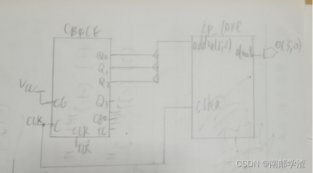
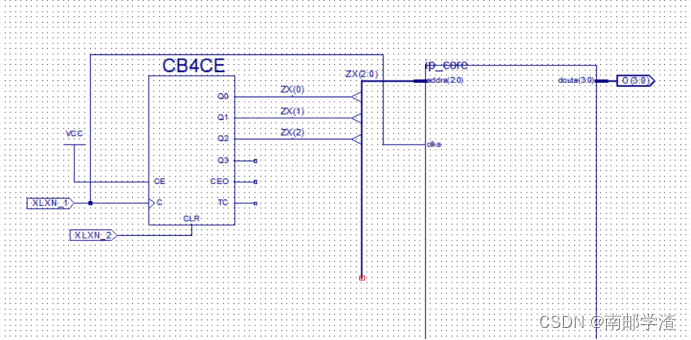
通过IP核产生位宽为4bit、存储深度为8的只读存储器,对该ROM进行数据的写入,写入4路序列信号:F1=11001100,F2=11110000,F3=11011011,F4=10111001。同时需要一个模8计数器对ROM的地址进行驱动,以读出写入ROM的设计数据。
(3)实验电路图
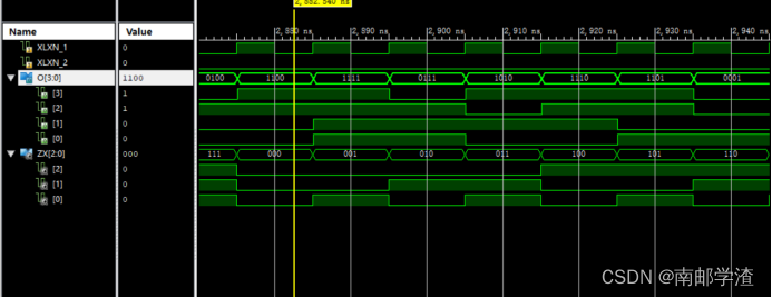
(4)实验数据分析和实验结果
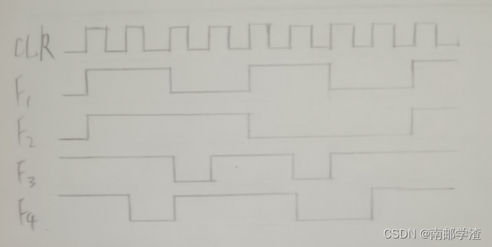
示波器显示:F1=11001100,F2=11110000,F3=11011011,F4=10111001
