前言
本篇博客主要是
理解OLED屏显和汉字点阵编码原理,使用STM32F103的SPI或IIC接口实现以下功能:
1、显示自己的学号和姓名;
2、显示AHT20的温度和湿度;
3、上下或左右的滑动显示长字符,比如“Hello,欢迎来到重庆交通大学物联网205实训室!”或者一段歌词或诗词(使用硬件刷屏模式)。
另附:
0.96寸SPI_OLED模块配套资料包:
链接:https://pan.baidu.com/s/1mdLUqBqQZ_gMOzDHM7rU2g
提取码:1234
取字模的工具:
链接:https://pan.baidu.com/s/1ZSrDvhP-mwLQB9F0X_uLlQ
提取码:1234
一、了解SPI
1、SPI定义
SPI(Serial Peripheral Interface)就是串行外围设备接口。
SPI,是一种高速的,全双工,同步的通信总线,并且在芯片的管脚上只占用四根线,节约了芯片的管脚。SPI 是一个环形总线结构,由 ss(cs)、sck、sdi、sdo 构成,时序主要是在 sck 的控制下,两个双向移位寄存器进行数据交换。
上升沿发送、下降沿接收、高位先发送。
上升沿到来的时候,sdo 上的电平将被发送到从设备的寄存器中。
下降沿到来的时候,sdi 上的电平将被接收到主设备的寄存器中。
2、组成
与I2C协议相同,把它分为物理层和协议层。
物理层
SPI 通讯使用 3 条总线及片选线,3 条总线分别为 SCK、MOSI、MISO,片选线为 NSS。
NSS :SPI 协议中没有设备地址,它使用 NSS 信号线来寻址,当主机要选择从设备时,把该从设备的 NSS 信号线设置为低电平,该从设备即被选中,即片选有效,接着主机开始与被选中的从设备进行 SPI通讯。
SCK (Serial Clock):时钟信号线,用于通讯数据同步。
MOSI (Master Output, Slave Input):主设备输出/从设备输入引脚。
MISO(Master Input,,Slave Output):主设备输入/从设备输出引脚。
协议层
与 I2C 的类似,SPI 协议定义了通讯的起始和停止信号、数据有效性、时钟同步等环节。
通讯的起始和停止信号
NSS 信号线由高变低,是 SPI 通讯的起始信号。NSS 是每个从机各自独占的信号线,当从机在自己的 NSS
线检测到起始信号后,就知道自己被主机选中了,开始准备与主机通讯。NSS 信号由低变高,是 SPI
通讯的停止信号,表示本次通讯结束,从机的选中状态被取消。
数据的有效性
MOSI 及 MISO 的数据在 SCK 的上升沿期间变化输出,在SCK 的下降沿时被采样。即在 SCK 的下降沿时刻MOSI 及 MISO
的数据有效,高电平时表示数据“1”,为低电平时表示数据“0”。在其它时刻,数据无效,MOSI及 MISO
为下一次表示数据做准备。(这只是对上图情况的分析,上图并不是唯一的通讯模式。)
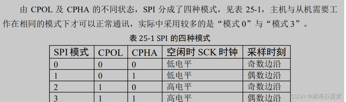
SPI的四种模式
二、OLED屏显和汉字点阵编码原理
1、汉字点阵编码原理
1、 在汉字的点阵字库中,每个字节的每个位都代表一个汉字的一个点,每个汉字都是由一个矩形的点阵组成,0代表没有,1代表有点,将0和1分别用不同颜色画出,就形成了一个汉字,常用的点阵矩阵有12×12, 14×14, 16×16三种字库。
2、 字库根据字节所表示点的不同有分为横向矩阵和纵向矩阵,目前多数的字库都是横向矩阵的存储方式(用得最多的应该是早期UCDOS字库),纵向矩阵一般是因为有某些液晶是采用纵向扫描显示法,为了提高显示速度,于是便把字库矩阵做成纵向,省得在显示时还要做矩阵转换。我们接下去所描述的都是指横向矩阵字库。
详细——–>
汉字点阵原理
2、OLED屏显
OLED(Organic Light Emitting Display,中文名有机发光显示器)是指有机半导体材料和发光材料在电场驱动下,通过载流子注入和复合导致发光的现象。其原理是用ITO透明电极和金属电极分别作为器件的阳极和阴极,在一定电压驱动下,电子和空穴分别从阴极和阳极注入到电子和空穴传输层,电子和空穴分别经过电子和空穴传输层迁移到发光层,并在发光层中相遇,形成激子并使发光分子激发,后者经过辐射弛豫而发出可见光。
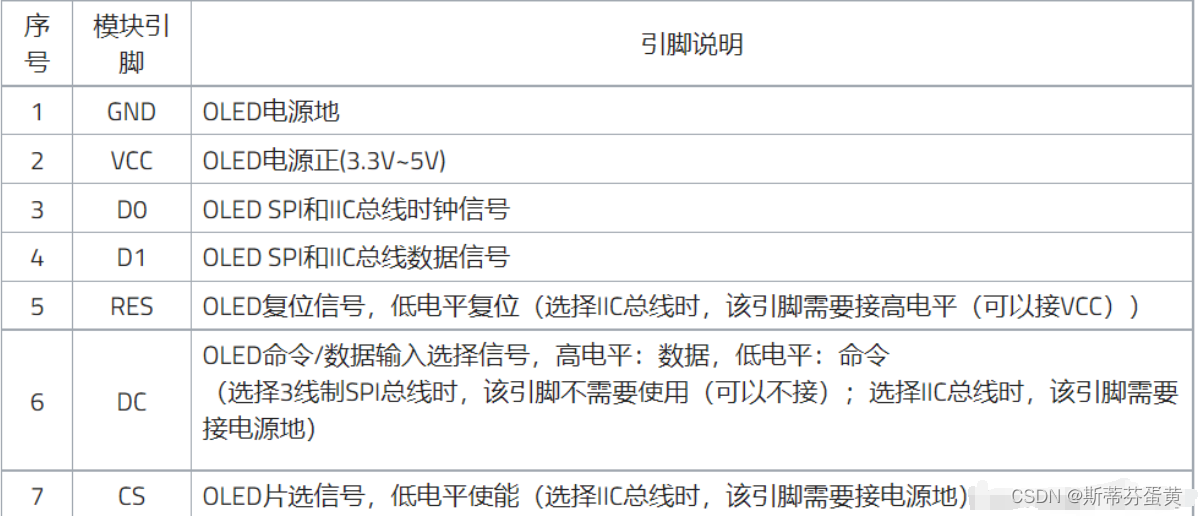
3、引脚说明
三、显示自己的学号和姓名
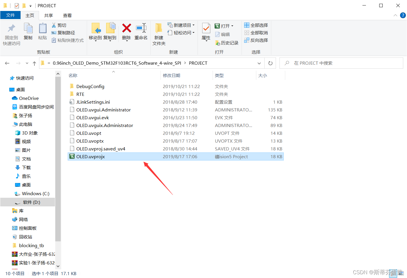
将此次实验所需要的demo下载下来。
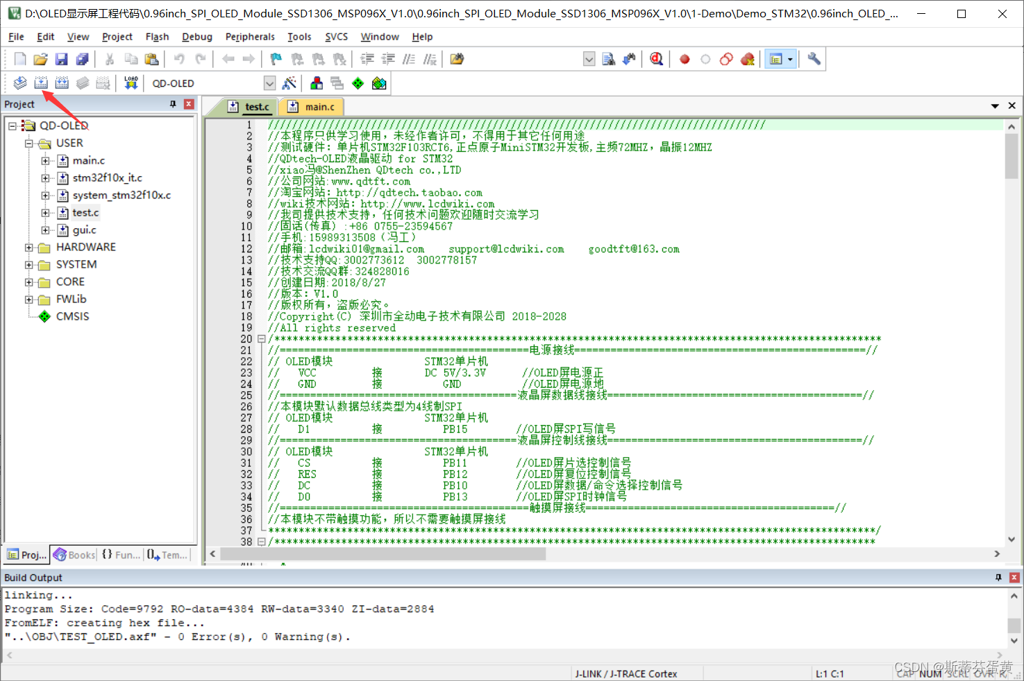
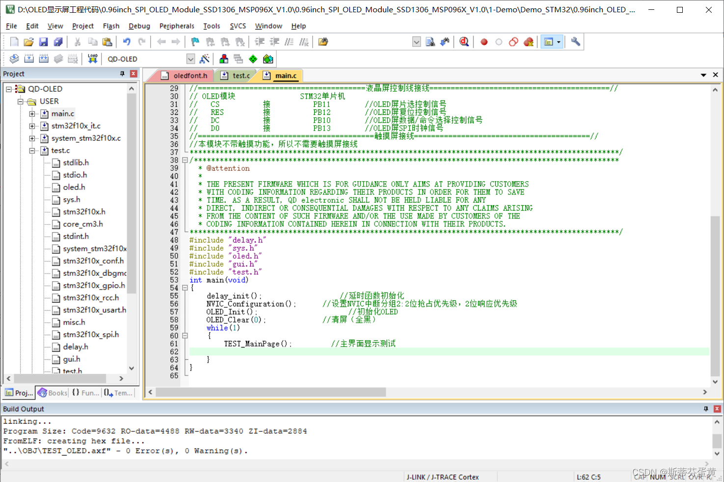
解压进入到工程目录下,双击文件打开keil进行代码修改
编译一次,这样.c文件下的文件才出来
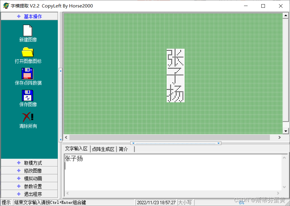
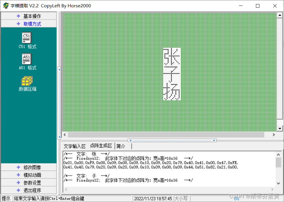
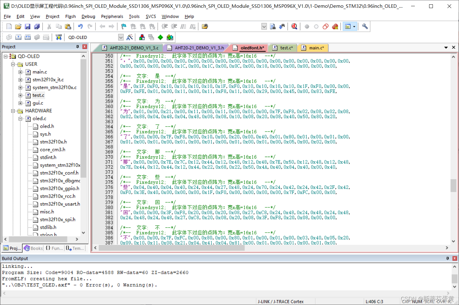
通过取字模软件,取到相应的汉字。
打开字模软件,输入自己想要的字,设置C51格式提取
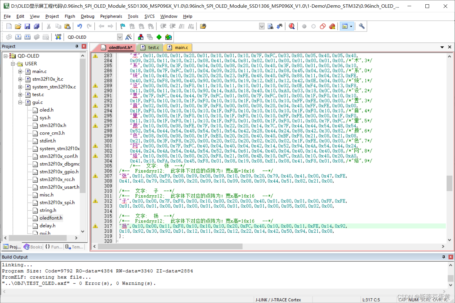
找到gui.c下的oledfont.h,将自己的字模复制进去
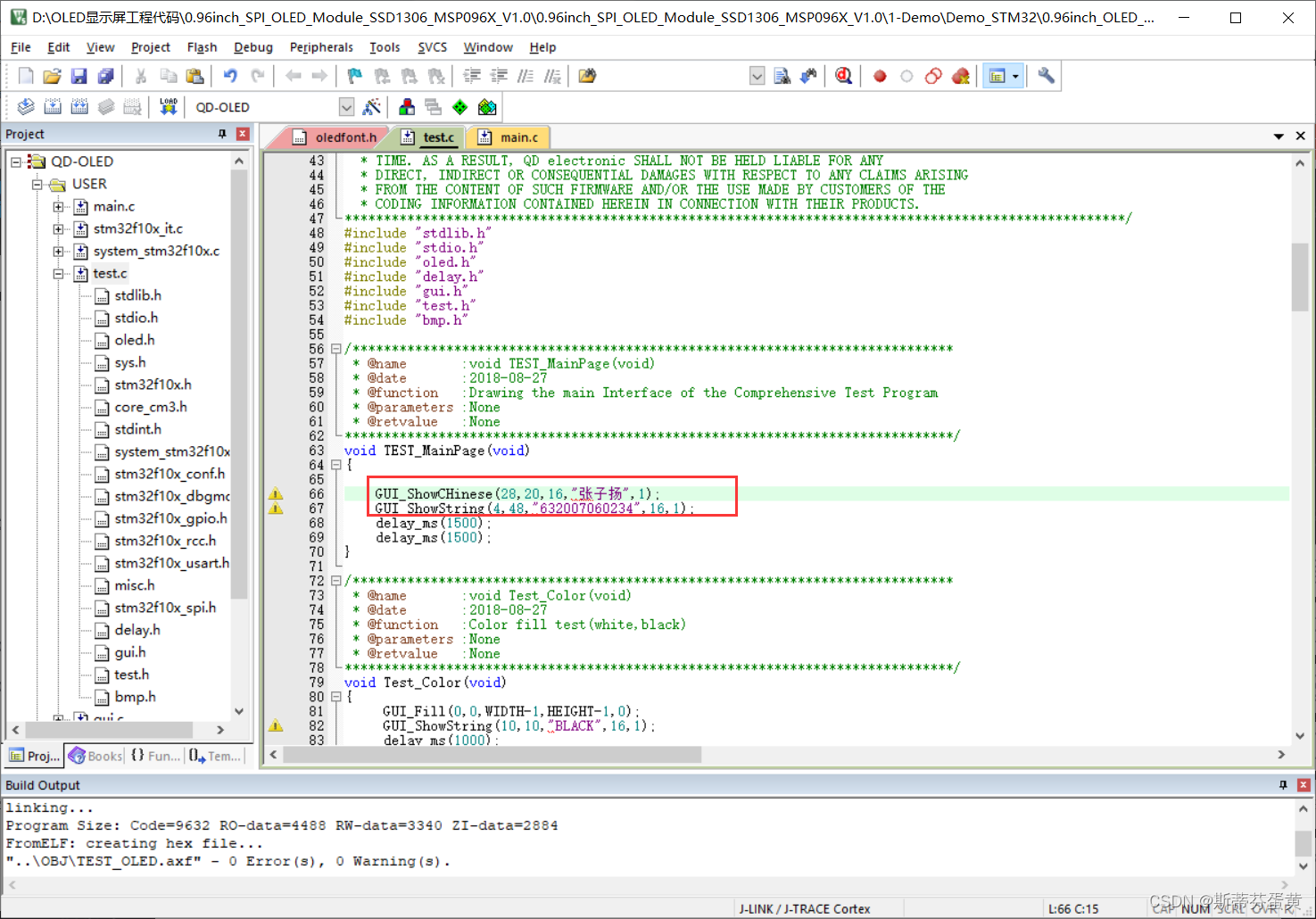
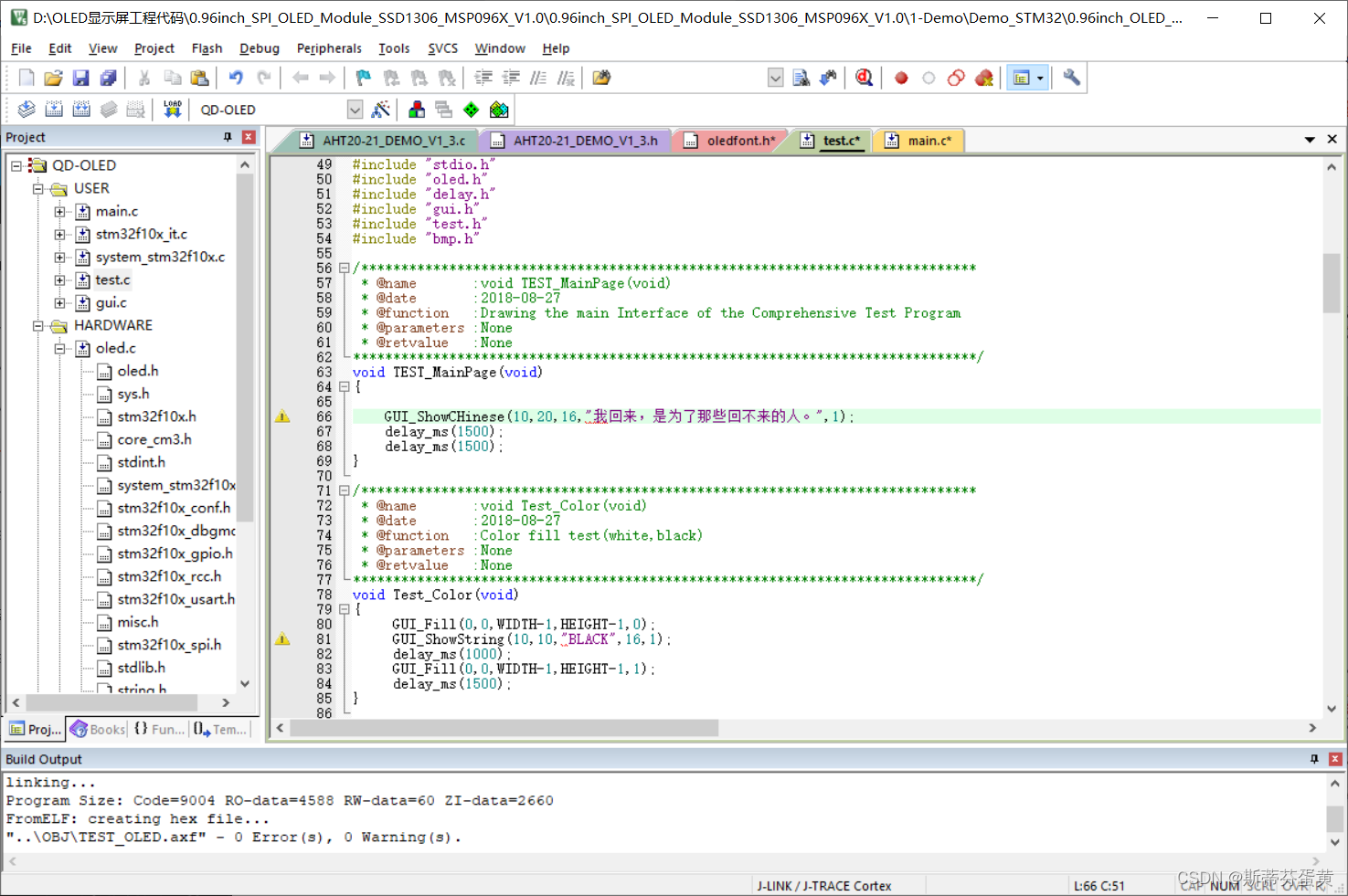
修改test.c
打开test.c,修改TEST_MainPage函数
修改main.c
效果

四、显示温湿度
仍然使用demo
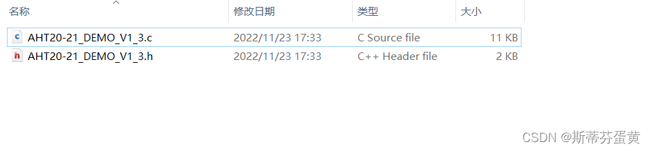
新建一个AHT20文件夹
在里面创建AHT20-21_DEMO_V1_3.c和AHT20-21_DEMO_V1_3.h两个空白文件。
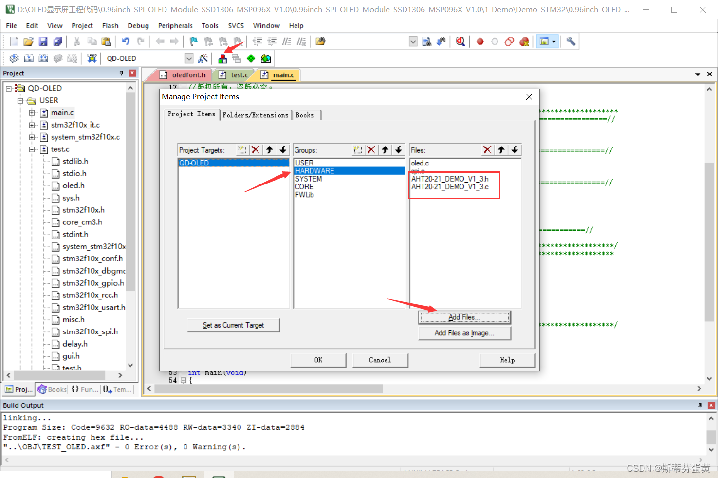
添加文件
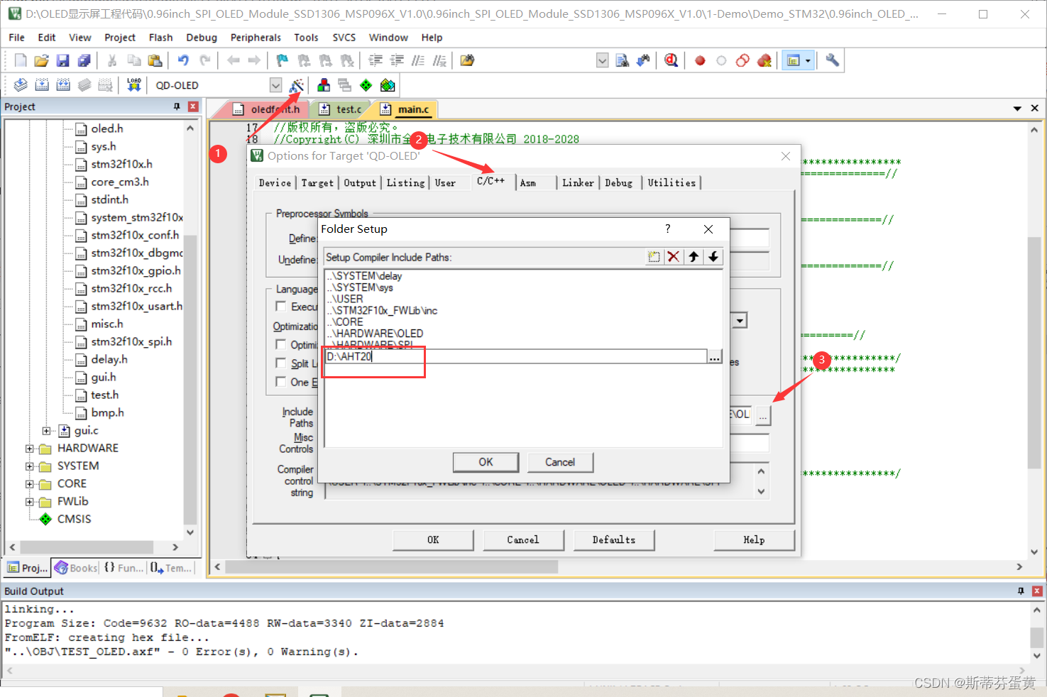
添加文件路径
写入AHT20-21_DEMO_V1_3.c文件
/*******************************************/
/*@??????У?????????????????          */
/*@????????????????????                */
/*@?汾??V1.2                              */
/*******************************************/


#include "AHT20-21_DEMO_V1_3.h"


void Delay_N10us(uint32_t t)//???????
{
  uint32_t k;

   while(t--)
  {
    for (k = 0; k < 2; k++);//110
  }
}

void SensorDelay_us(uint32_t t)//???????
{

	for(t = t-2; t>0; t--)
	{
		Delay_N10us(1);
	}
}

void Delay_4us(void)		//???????
{
	Delay_N10us(1);
	Delay_N10us(1);
	Delay_N10us(1);
	Delay_N10us(1);
}
void Delay_5us(void)		//???????
{
	Delay_N10us(1);
	Delay_N10us(1);
	Delay_N10us(1);
	Delay_N10us(1);
	Delay_N10us(1);

}

void Delay_1ms(uint32_t t)		//???????
{
   while(t--)
  {
    SensorDelay_us(1000);//???1ms
  }
}


//void AHT20_Clock_Init(void)		//???????
//{
//	RCC_APB2PeriphClockCmd(CC_APB2Periph_GPIOB,ENABLE);
//}

void SDA_Pin_Output_High(void)   //??PB7???????? ?? ????????????? PB7???I2C??SDA
{
	GPIO_InitTypeDef  GPIO_InitStruct;
	GPIO_InitStruct.GPIO_Mode = GPIO_Mode_Out_PP;//???????
	GPIO_InitStruct.GPIO_Pin = GPIO_Pin_7;
	GPIO_InitStruct.GPIO_Speed = GPIO_Speed_50MHz;
	GPIO_Init(GPIOB,& GPIO_InitStruct);
	GPIO_SetBits(GPIOB,GPIO_Pin_7);
}

void SDA_Pin_Output_Low(void)  //??P7????????  ???????????
{

	GPIO_InitTypeDef  GPIO_InitStruct;
	GPIO_InitStruct.GPIO_Mode = GPIO_Mode_Out_PP;//???????
	GPIO_InitStruct.GPIO_Pin = GPIO_Pin_7;
	GPIO_InitStruct.GPIO_Speed = GPIO_Speed_50MHz;
	GPIO_Init(GPIOB,& GPIO_InitStruct);
	GPIO_ResetBits(GPIOB,GPIO_Pin_7);
}

void SDA_Pin_IN_FLOATING(void)  //SDA?????????????
{

	GPIO_InitTypeDef  GPIO_InitStruct;
	GPIO_InitStruct.GPIO_Mode = GPIO_Mode_IN_FLOATING;//
	GPIO_InitStruct.GPIO_Pin = GPIO_Pin_7;
	GPIO_InitStruct.GPIO_Speed = GPIO_Speed_50MHz;
	GPIO_Init( GPIOB,&GPIO_InitStruct);
}

void SCL_Pin_Output_High(void) //SCL?????????P6???I2C??SCL
{
	GPIO_SetBits(GPIOB,GPIO_Pin_6);
}

void SCL_Pin_Output_Low(void) //SCL???????
{
	GPIO_ResetBits(GPIOB,GPIO_Pin_6);
}

void Init_I2C_Sensor_Port(void) //?????I2C???,????????
{
	GPIO_InitTypeDef  GPIO_InitStruct;
	GPIO_InitStruct.GPIO_Mode = GPIO_Mode_Out_PP;//???????
	GPIO_InitStruct.GPIO_Pin = GPIO_Pin_7;
	GPIO_InitStruct.GPIO_Speed = GPIO_Speed_50MHz;
	GPIO_Init(GPIOB,& GPIO_InitStruct);
	GPIO_SetBits(GPIOB,GPIO_Pin_15);//???????

	GPIO_InitStruct.GPIO_Mode = GPIO_Mode_Out_PP;//???????
	GPIO_InitStruct.GPIO_Pin = GPIO_Pin_6;
	GPIO_InitStruct.GPIO_Speed = GPIO_Speed_50MHz;
	GPIO_Init(GPIOB,& GPIO_InitStruct);
	GPIO_SetBits(GPIOB,GPIO_Pin_15);//???????

}
void I2C_Start(void)		 //I2C????????START???
{
	SDA_Pin_Output_High();
	SensorDelay_us(8);
	SCL_Pin_Output_High();
	SensorDelay_us(8);
	SDA_Pin_Output_Low();
	SensorDelay_us(8);
	SCL_Pin_Output_Low();
	SensorDelay_us(8);
}


void AHT20_WR_Byte(uint8_t Byte) //??AHT20д??????
{
	uint8_t Data,N,i;
	Data=Byte;
	i = 0x80;
	for(N=0;N<8;N++)
	{
		SCL_Pin_Output_Low();
		Delay_4us();
		if(i&Data)
		{
			SDA_Pin_Output_High();
		}
		else
		{
			SDA_Pin_Output_Low();
		}

    SCL_Pin_Output_High();
		Delay_4us();
		Data <<= 1;

	}
	SCL_Pin_Output_Low();
	SensorDelay_us(8);
	SDA_Pin_IN_FLOATING();
	SensorDelay_us(8);
}


uint8_t AHT20_RD_Byte(void)//??AHT20?????????
{
	uint8_t Byte,i,a;
	Byte = 0;
	SCL_Pin_Output_Low();
	SDA_Pin_IN_FLOATING();
	SensorDelay_us(8);
	for(i=0;i<8;i++)
	{
    SCL_Pin_Output_High();
		Delay_5us();
		a=0;
		if(GPIO_ReadInputDataBit(GPIOB,GPIO_Pin_7)) a=1;
		Byte = (Byte<<1)|a;
		SCL_Pin_Output_Low();
		Delay_5us();
	}
  SDA_Pin_IN_FLOATING();
	SensorDelay_us(8);
	return Byte;
}


uint8_t Receive_ACK(void)   //??AHT20????л??ACK
{
	uint16_t CNT;
	CNT = 0;
	SCL_Pin_Output_Low();
	SDA_Pin_IN_FLOATING();
	SensorDelay_us(8);
	SCL_Pin_Output_High();
	SensorDelay_us(8);
	while((GPIO_ReadInputDataBit(GPIOB,GPIO_Pin_7))  && CNT < 100)
	CNT++;
	if(CNT == 100)
	{
		return 0;
	}
 	SCL_Pin_Output_Low();
	SensorDelay_us(8);
	return 1;
}

void Send_ACK(void)		  //???????ACK???
{
	SCL_Pin_Output_Low();
	SensorDelay_us(8);
	SDA_Pin_Output_Low();
	SensorDelay_us(8);
	SCL_Pin_Output_High();
	SensorDelay_us(8);
	SCL_Pin_Output_Low();
	SensorDelay_us(8);
	SDA_Pin_IN_FLOATING();
	SensorDelay_us(8);
}

void Send_NOT_ACK(void)	//?????????ACK
{
	SCL_Pin_Output_Low();
	SensorDelay_us(8);
	SDA_Pin_Output_High();
	SensorDelay_us(8);
	SCL_Pin_Output_High();
	SensorDelay_us(8);
	SCL_Pin_Output_Low();
	SensorDelay_us(8);
    SDA_Pin_Output_Low();
	SensorDelay_us(8);
}

void Stop_I2C(void)	  //???Э?????
{
	SDA_Pin_Output_Low();
	SensorDelay_us(8);
	SCL_Pin_Output_High();
	SensorDelay_us(8);
	SDA_Pin_Output_High();
	SensorDelay_us(8);
}

uint8_t AHT20_Read_Status(void)//???AHT20?????????
{

	uint8_t Byte_first;
	I2C_Start();
	AHT20_WR_Byte(0x71);
	Receive_ACK();
	Byte_first = AHT20_RD_Byte();
	Send_NOT_ACK();
	Stop_I2C();
	return Byte_first;
}

uint8_t AHT20_Read_Cal_Enable(void)  //???cal enableλ????????
{
	uint8_t val = 0;//ret = 0,
  val = AHT20_Read_Status();
	 if((val & 0x68)==0x08)
		 return 1;
   else  return 0;
 }

void AHT20_SendAC(void) //??AHT20????AC????
{

	I2C_Start();
	AHT20_WR_Byte(0x70);
	Receive_ACK();
	AHT20_WR_Byte(0xac);//0xAC???????
	Receive_ACK();
	AHT20_WR_Byte(0x33);
	Receive_ACK();
	AHT20_WR_Byte(0x00);
	Receive_ACK();
	Stop_I2C();

}

//CRCУ???????CRC8/MAXIM
//???????X8+X5+X4+1
//Poly??0011 0001  0x31
//??λ?????????? 1000 1100 0x8c
//C???????
uint8_t Calc_CRC8(uint8_t *message,uint8_t Num)
{
        uint8_t i;
        uint8_t byte;
        uint8_t crc=0xFF;
  for(byte=0; byte<Num; byte++)
  {
    crc^=(message[byte]);
    for(i=8;i>0;--i)
    {
      if(crc&0x80) crc=(crc<<1)^0x31;
      else crc=(crc<<1);
    }
  }
        return crc;
}

void AHT20_Read_CTdata(uint32_t *ct) //???CRCУ?飬?????AHT20?????????????
{
	volatile uint8_t  Byte_1th=0;
	volatile uint8_t  Byte_2th=0;
	volatile uint8_t  Byte_3th=0;
	volatile uint8_t  Byte_4th=0;
	volatile uint8_t  Byte_5th=0;
	volatile uint8_t  Byte_6th=0;
	 uint32_t RetuData = 0;
	uint16_t cnt = 0;
	AHT20_SendAC();//??AHT10????AC????
	Delay_1ms(80);//???80ms????
    cnt = 0;
	while(((AHT20_Read_Status()&0x80)==0x80))//?????bit[7]?0?????????????????1????????
	{
		SensorDelay_us(1508);
		if(cnt++>=100)
		{
		 break;
		 }
	}
	I2C_Start();
	AHT20_WR_Byte(0x71);
	Receive_ACK();
	Byte_1th = AHT20_RD_Byte();//?????????????0x98,?????????bit[7]?1?????0x1C??????0x0C??????0x08????????????bit[7]?0
	Send_ACK();
	Byte_2th = AHT20_RD_Byte();//???
	Send_ACK();
	Byte_3th = AHT20_RD_Byte();//???
	Send_ACK();
	Byte_4th = AHT20_RD_Byte();//???/???
	Send_ACK();
	Byte_5th = AHT20_RD_Byte();//???
	Send_ACK();
	Byte_6th = AHT20_RD_Byte();//???
	Send_NOT_ACK();
	Stop_I2C();

	RetuData = (RetuData|Byte_2th)<<8;
	RetuData = (RetuData|Byte_3th)<<8;
	RetuData = (RetuData|Byte_4th);
	RetuData =RetuData >>4;
	ct[0] = RetuData;//???
	RetuData = 0;
	RetuData = (RetuData|Byte_4th)<<8;
	RetuData = (RetuData|Byte_5th)<<8;
	RetuData = (RetuData|Byte_6th);
	RetuData = RetuData&0xfffff;
	ct[1] =RetuData; //???

}


void AHT20_Read_CTdata_crc(uint32_t *ct) //CRCУ??????AHT20?????????????
{
	volatile uint8_t  Byte_1th=0;
	volatile uint8_t  Byte_2th=0;
	volatile uint8_t  Byte_3th=0;
	volatile uint8_t  Byte_4th=0;
	volatile uint8_t  Byte_5th=0;
	volatile uint8_t  Byte_6th=0;
	volatile uint8_t  Byte_7th=0;
	 uint32_t RetuData = 0;
	 uint16_t cnt = 0;
	// uint8_t  CRCDATA=0;
	 uint8_t  CTDATA[6]={0};//????CRC????????

	AHT20_SendAC();//??AHT10????AC????
	Delay_1ms(80);//???80ms????
    cnt = 0;
	while(((AHT20_Read_Status()&0x80)==0x80))//?????bit[7]?0?????????????????1????????
	{
		SensorDelay_us(1508);
		if(cnt++>=100)
		{
		 break;
		}
	}

	I2C_Start();

	AHT20_WR_Byte(0x71);
	Receive_ACK();
	CTDATA[0]=Byte_1th = AHT20_RD_Byte();//?????????????0x98,?????????bit[7]?1?????0x1C??????0x0C??????0x08????????????bit[7]?0
	Send_ACK();
	CTDATA[1]=Byte_2th = AHT20_RD_Byte();//???
	Send_ACK();
	CTDATA[2]=Byte_3th = AHT20_RD_Byte();//???
	Send_ACK();
	CTDATA[3]=Byte_4th = AHT20_RD_Byte();//???/???
	Send_ACK();
	CTDATA[4]=Byte_5th = AHT20_RD_Byte();//???
	Send_ACK();
	CTDATA[5]=Byte_6th = AHT20_RD_Byte();//???
	Send_ACK();
	Byte_7th = AHT20_RD_Byte();//CRC????
	Send_NOT_ACK();                           //???: ????????NAK
	Stop_I2C();

	if(Calc_CRC8(CTDATA,6)==Byte_7th)
	{
	RetuData = (RetuData|Byte_2th)<<8;
	RetuData = (RetuData|Byte_3th)<<8;
	RetuData = (RetuData|Byte_4th);
	RetuData =RetuData >>4;
	ct[0] = RetuData;//???
	RetuData = 0;
	RetuData = (RetuData|Byte_4th)<<8;
	RetuData = (RetuData|Byte_5th)<<8;
	RetuData = (RetuData|Byte_6th);
	RetuData = RetuData&0xfffff;
	ct[1] =RetuData; //???

	}
	else
	{
		ct[0]=0x00;
		ct[1]=0x00;//У??????????????????????????????
	}//CRC????
}


void AHT20_Init(void)   //?????AHT20
{
	Init_I2C_Sensor_Port();
	I2C_Start();
	AHT20_WR_Byte(0x70);
	Receive_ACK();
	AHT20_WR_Byte(0xa8);//0xA8????NOR??????
	Receive_ACK();
	AHT20_WR_Byte(0x00);
	Receive_ACK();
	AHT20_WR_Byte(0x00);
	Receive_ACK();
	Stop_I2C();

	Delay_1ms(10);//???10ms????

	I2C_Start();
	AHT20_WR_Byte(0x70);
	Receive_ACK();
	AHT20_WR_Byte(0xbe);//0xBE?????????AHT20????????????0xBE,   AHT10????????????0xE1
	Receive_ACK();
	AHT20_WR_Byte(0x08);//???????bit[3]??1???У????
	Receive_ACK();
	AHT20_WR_Byte(0x00);
	Receive_ACK();
	Stop_I2C();
	Delay_1ms(10);//???10ms????
}
void JH_Reset_REG(uint8_t addr)
{

	uint8_t Byte_first,Byte_second,Byte_third;
	I2C_Start();
	AHT20_WR_Byte(0x70);//?????0x70
	Receive_ACK();
	AHT20_WR_Byte(addr);
	Receive_ACK();
	AHT20_WR_Byte(0x00);
	Receive_ACK();
	AHT20_WR_Byte(0x00);
	Receive_ACK();
	Stop_I2C();

	Delay_1ms(5);//???5ms????
	I2C_Start();
	AHT20_WR_Byte(0x71);//
	Receive_ACK();
	Byte_first = AHT20_RD_Byte();
	Send_ACK();
	Byte_second = AHT20_RD_Byte();
	Send_ACK();
	Byte_third = AHT20_RD_Byte();
	Send_NOT_ACK();
	Stop_I2C();

    Delay_1ms(10);//???10ms????
	I2C_Start();
	AHT20_WR_Byte(0x70);///
	Receive_ACK();
	AHT20_WR_Byte(0xB0|addr);//?????????
	Receive_ACK();
	AHT20_WR_Byte(Byte_second);
	Receive_ACK();
	AHT20_WR_Byte(Byte_third);
	Receive_ACK();
	Stop_I2C();

	Byte_second=0x00;
	Byte_third =0x00;
}

void AHT20_Start_Init(void)
{
	JH_Reset_REG(0x1b);
	JH_Reset_REG(0x1c);
	JH_Reset_REG(0x1e);
}
写入AHT20-21_DEMO_V1_3.h文件
#ifndef _AHT20_DEMO_
#define _AHT20_DEMO_

#include "stm32f10x.h"

void Delay_N10us(uint32_t t);//???????
void SensorDelay_us(uint32_t t);//???????
void Delay_4us(void);		//???????
void Delay_5us(void);		//???????
void Delay_1ms(uint32_t t);
void AHT20_Clock_Init(void);		//???????
void SDA_Pin_Output_High(void)  ; //??PB15???????? ?? ????????????? PB15???I2C??SDA
void SDA_Pin_Output_Low(void);  //??P15????????  ???????????
void SDA_Pin_IN_FLOATING(void);  //SDA?????????????
void SCL_Pin_Output_High(void); //SCL?????????P14???I2C??SCL
void SCL_Pin_Output_Low(void); //SCL???????
void Init_I2C_Sensor_Port(void); //?????I2C???,????????
void I2C_Start(void);		 //I2C????????START???
void AHT20_WR_Byte(uint8_t Byte); //??AHT20д??????
uint8_t AHT20_RD_Byte(void);//??AHT20?????????
uint8_t Receive_ACK(void);   //??AHT20????л??ACK
void Send_ACK(void)	;	  //???????ACK???
void Send_NOT_ACK(void);	//?????????ACK
void Stop_I2C(void);	  //???Э?????
uint8_t AHT20_Read_Status(void);//???AHT20?????????
uint8_t AHT20_Read_Cal_Enable(void);  //???cal enableλ????????
void AHT20_SendAC(void); //??AHT20????AC????
uint8_t Calc_CRC8(uint8_t *message,uint8_t Num);
void AHT20_Read_CTdata(uint32_t *ct); //???CRCУ?飬?????AHT20?????????????
void AHT20_Read_CTdata_crc(uint32_t *ct); //CRCУ??????AHT20?????????????
void AHT20_Init(void);   //?????AHT20
void JH_Reset_REG(uint8_t addr);///???ü????
void AHT20_Start_Init(void);///?????????????????????
#endif
修改main.c
#include "delay.h"
#include "sys.h"
#include "oled.h"
#include "gui.h"
#include "test.h"
#include "AHT20-21_DEMO_V1_3.h"
void TEST_MainPage1(int c1,int t1)
{

    GUI_ShowCHinese(5,30,16,"湿度",1);
    GUI_ShowCHinese(5,45,16,"温度",1);
	GUI_ShowNum(35,30,c1/10,4,16,1);
	GUI_ShowNum(35,45,t1/10,4,16,1);
	Delay_1ms(1000);
}
volatile int  c1,t1;
uint32_t CT_data[2]={0,0};
u8 temp[10];
u8 hum[10];
int main(void)
{
	delay_init();	    	       //延时函数初始化
	OLED_Init();			         //初始化OLED
	OLED_Clear(0);             //清屏(全黑)

	/***********************************************************************************/
	/**///①刚上电,产品芯片内部就绪需要时间,延时100~500ms,建议500ms
	/***********************************************************************************/
	AHT20_Init();
	Delay_1ms(500);
	/***********************************************************************************/
	/**///②上电第一次发0x71读取状态字,判断状态字是否为0x18,如果不是0x18,进行寄存器初始化
	/***********************************************************************************/

	if((AHT20_Read_Status()&0x18)!=0x18)
	{
		AHT20_Start_Init(); //重新初始化寄存器
		Delay_1ms(10);
	}


	//NVIC_Configuration(); 	   //设置NVIC中断分组2:2位抢占优先级,2位响应优先级
   OLED_WR_Byte(0x2E,OLED_CMD); //关闭滚动

	OLED_WR_Byte(0x27,OLED_CMD); //水平向左或者右滚动 26/27

	OLED_WR_Byte(0x00,OLED_CMD); //虚拟字节

	OLED_WR_Byte(0x00,OLED_CMD); //起始页 0

	OLED_WR_Byte(0x07,OLED_CMD); //滚动时间间隔

	OLED_WR_Byte(0x09,OLED_CMD); //终止页 2

	OLED_WR_Byte(0x00,OLED_CMD); //虚拟字节

	OLED_WR_Byte(0xFF,OLED_CMD); //虚拟字节
	while(1)
	{
		//AHT20_Read_CTdata(CT_data);       //不经过CRC校验,直接读取AHT20的温度和湿度数据    推荐每隔大于1S读一次
    AHT20_Read_CTdata_crc(CT_data);  //crc校验后,读取AHT20的温度和湿度数据
	  c1 = CT_data[0]*100*10/1024/1024;  //计算得到湿度值c1(放大了10倍)
	  t1 = CT_data[1]*200*10/1024/1024-500;//计算得到温度值t1(放大了10倍)
		TEST_MainPage1(c1,t1);         //界面显示
		OLED_WR_Byte(0x2F,OLED_CMD); //开启滚动
	  Delay_1ms(2000);

	}
}
效果

五、左右的滑动显示长字符
仍然使用demo,与上文三相同,只需要修改main.c和test.c并加入字模即可
修改main.c
#include "delay.h"
#include "sys.h"
#include "oled.h"
#include "gui.h"
#include "test.h"
int main(void)
{
	delay_init();	    	       //延时函数初始化
	NVIC_Configuration(); 	   //设置NVIC中断分组2:2位抢占优先级,2位响应优先级
	OLED_Init();			         //初始化OLED
	OLED_Clear(0);             //清屏(全黑)
	OLED_WR_Byte(0x2E,OLED_CMD);        //关闭滚动
  OLED_WR_Byte(0x27,OLED_CMD);        //水平向左或者右滚动 26/27
  OLED_WR_Byte(0x00,OLED_CMD);        //虚拟字节
	OLED_WR_Byte(0x00,OLED_CMD);        //起始页 0
	OLED_WR_Byte(0x07,OLED_CMD);        //滚动时间间隔
	OLED_WR_Byte(0x07,OLED_CMD);        //终止页 7
	OLED_WR_Byte(0x00,OLED_CMD);        //虚拟字节
	OLED_WR_Byte(0xFF,OLED_CMD);        //虚拟字节
	TEST_MainPage();
	OLED_WR_Byte(0x2F,OLED_CMD);        //开启滚动
	while(1)
	{
		//TEST_MainPage();         //主界面显示测试


		//TEST_MainPage();
		/*OLED_Clear(0);
		Test_Color();            //刷屏测试
		OLED_Clear(0);
		Test_Rectangular();      //矩形绘制测试
		OLED_Clear(0);
		Test_Circle();           //圆形绘制测试
		OLED_Clear(0);
		Test_Triangle();         //三角形绘制测试
		OLED_Clear(0);

		TEST_English();          //英文显示测试
		OLED_Clear(0);
		TEST_Number_Character(); //数字和符号显示测试
		OLED_Clear(0);

		TEST_Chinese();          //中文显示测试
		OLED_Clear(0);
		TEST_BMP();              //BMP单色图片显示测试
		OLED_Clear(0);
		TEST_Menu1();            //菜单1显示测试
		OLED_Clear(0);
		TEST_Menu2();            //菜单2显示测试
		OLED_Clear(0); */
	}
}
修改test.c
加入字模
效果
滑动显示
六、总结
这次实验主要是用标准库做的,之前都是用hal库做。本次实验主要是复习了SPI协议和汉字点阵的原理及应用。在完成的过程中还是有许多困难的,比如编译出错,但经过查找资料还是解决了。总之,本次实验还是有颇多收获的。